
Spot Elevation
Updated on: October 20, 2025
Quick video
- Placing a Spot Elevation
- Changing the Spot Elevation Style
- Placing a Spot Elevation Relative to an Existing Spot Elevation
- Placing Multiple Spot Elevations Automatically Using Grid Placement
- Placing Spot Elevations Along a Straight Line or Polyline
- Placing One Callout With Multiple Elevations
- Working with Spot Elevation Callouts in the Civil and Survey Manager
- Assigning a Z Elevation to a Spot Elevation (Spot Elevation Z Align)
- Slope Callouts
- Correcting Scale With Spot Elevations
- Troubleshooting
Our Spot Elevation tool allows you to place elevation callouts directly into your drawing. You can also use this tool to automatically determine a Spot Elevation in relation to an existing one, given a slope between the two.
Spot Elevation callouts are now multileaders (MLeaders), allowing for easier editing and moving.
Our Spot Elevation tool only uses either feet or meters. It does not use inches or millimeters.
Please note that we've discontinued the FX_OLDSPOTELEVATION command for using the old-style Spot Elevation callouts, as it was causing issues with our code.
Placing a Spot Elevation
Open our Spot Elevation tool:

F/X Site ribbon, Spot Elevation flyout

F/X Irrigation ribbon, Spot Elevation flyout

F/X Site and F/X Irrigation menus, Spot Elevation option (F/X Site menu shown as an example)
or type FX_PlaceSpotElevation in the Command line
When you open the Spot Elevation tool, you'll be prompted to place an Arrow point. You can either:
- Select a point in your plan and place an elevation callout manually.
- Select an existing contour line with a Z elevation. The Spot Elevation tool will read that elevation and enter it automatically into the Spot Elevation callout you place.
Placing a Single Spot Elevation Manually
Click a point in your drawing to assign it with a Spot Elevation.

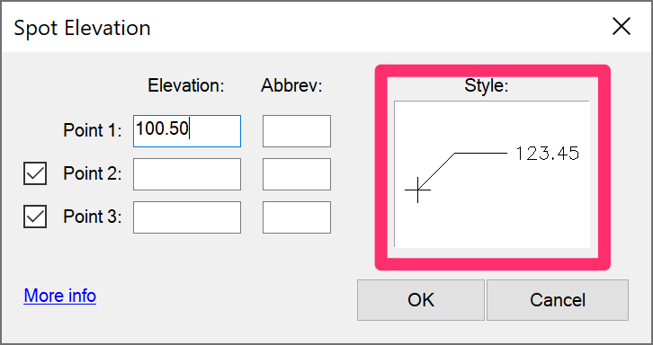
The Spot Elevation dialog box will open. In the Point 1 field, enter an elevation for the Spot Elevation callout you want to place.
If you want, you can enter an abbreviation for the elevation callout in the Abbrev field. The abbreviation will appear at the end of the callout.
Spot Elevation abbreviations usually consist of two letters that define the point. For instance: FG=Finished Grade, TW=Top of Wall, TP=Top of Paving, etc.
The Point 2 and Point 3 fields allow you to place multiple elevations in one callout. If you just want to enter a single elevation, use the Point 1 field.
Move the mouse to determine the angle of orientation to the Spot Elevation callout and the length of its leader. Click to set the angle and leader length.
Spot Elevations are no longer set to 45-degree increments.
A Spot Elevation callout will appear and extend from the cursor.


Move the mouse to adjust the orientation of the Spot Elevation callout.
Continuing to move the mouse moves the Spot Elevation callout.
While moving the mouse for Spot Elevation orientation, you can also drag it away from the initial elevation point to make the elevation leader line longer to avoid text or other objects.

After determining the orientation and the length of the leader, click to place the Spot Elevation.

You'll now see the Spot Elevation callout in your drawing.
Note that the Spot Elevation is a multileader (MLeader). Because MLeader arrows rotate with the leader line in CAD, our Spot Elevation tool will replace the arrow with a rotated block immediately after placement to align with the World UCS or custom UCS.

Continuing to move the mouse moves the Spot Elevation callout.
After placing, you can move the Spot Elevation callout around freely.

To correct any rotated X or + arrows, use the Refresh button in the Civil and Survey Manager, Spot Elevation tab.


Assigning a Spot Elevation to a Contour Line
To assign a Spot Elevation to a contour line in your drawing, open the Spot Elevation tool and, when prompted to select an arrow point, click to select a contour line with a Z elevation. The Spot Elevation tool will read that elevation and automatically apply it to the elevation callout.
Accounting for Elevation Changes in an Irrigation Design
Quick video

You can use Spot Elevations to reflect elevation changes in your irrigation designs – which in turn can affect pressure rates, pipe sizes, etc. Any head or valve will automatically look for the NEAREST Spot Elevation and assume the head or valve is at that elevation. Because of this feature, we recommend placing Spot Elevations generously when using them in an irrigation design. You can choose to use Spot Elevations when sizing your lateral pipes. More information
Changing the Spot Elevation Style
Selecting a Spot Elevation Style
Our Spot Elevation tool allows you to choose from a number of callout styles.
The style that's currently selected is shown as a thumbnail preview in the Style area of the Spot Elevation dialog box. To select a new style, click this thumbnail.
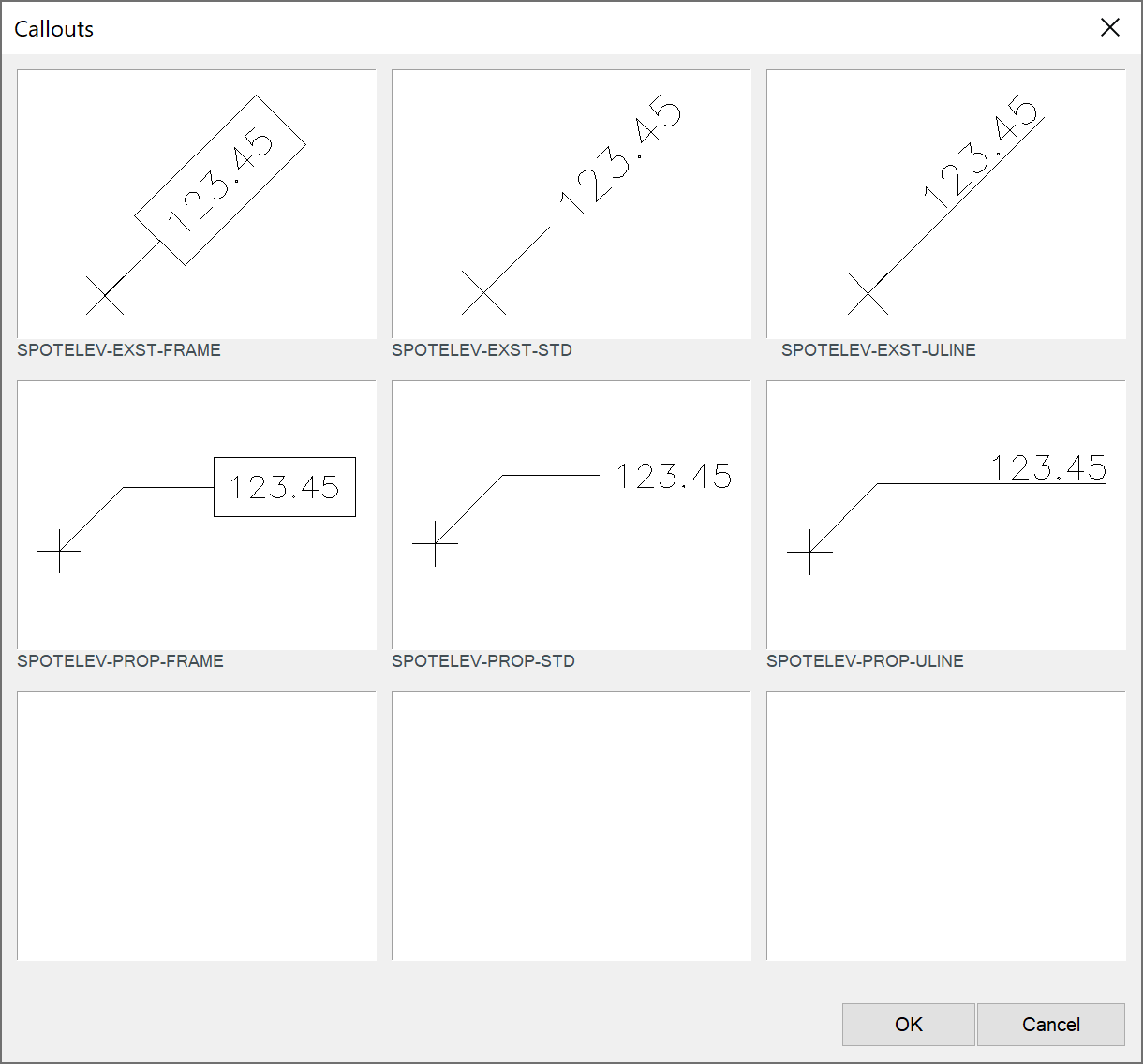
The Callouts dialog box will open. Select a style for your Spot Elevations and click OK.
Don't like any of the default styles? You're free to edit the Spot Elevation source blocks to your liking.
Changing the Text Style
You can use the Block Editor to confirm which Text Style is being used for your Spot Elevations. Our software uses the Text Style Callout Light as the default style for Spot Elevations.
If needed, you can edit the Callout Light style using the Text Manager.
As with any of our default Text Styles, keep in mind that editing Callout Light will change the style of ALL text placed using our software that is assigned the Callout Light style.
If you've already placed some Spot Elevation callouts and need to edit the text (such as changing the size or color), you'll also need to make the change in the MLeader style.
Follow our steps to edit the MLeader styles.
Select the option to Modify the current MLeader Style.
Select the Content tab in the Modify Multileader Style. You can then make the necessary changes to the style.
The example to the right shows the menus you can use to change the Text color and Text height.
Click OK when finished.

Changing the Multileader Style or Color
You can also change the style of the Multileader (MLeader) that forms your Spot Elevation callouts' leaders, arrows, and text. For example, you might want to change the color of the text, leader, and arrow so they all match. For instructions, see our MLeader Styles documentation.
Further Customizing Spot Elevation Callouts
We offer the option to create your own Spot Elevation callouts with attributes. More information
Correcting Scale With Spot Elevations
If your Spot Elevation text is coming in too big or too small in relation to the rest of your drawing, you're most likely facing a scaling issue. If this is the case, follow our steps to correct scale in callouts.
Placing a Spot Elevation Relative to an Existing Spot Elevation
After you've placed one Spot Elevation callout, you can place additional callouts and have their elevations calculate automatically based on the slope from another existing elevation.
If you have at least one existing Spot Elevation in a drawing, when you place another Spot Elevation the Command Line will indicate: Arrow point, [Relative to existing/Continue from last/Grid placement].
You can either:
- Type R to make the next point relative to another existing Spot Elevation. The cursor will turn into a pickbox, which you can use to select one of your existing Spot Elevation callouts. The new Spot Elevation will have its elevation measured relative to the one you selected.
- Type C to make the next point continue from the last point entered.
After you type R or C, the Slope dialog box will open.
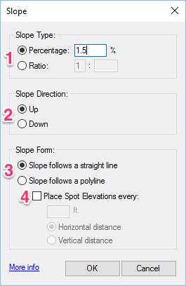
1. Slope Type options:
- Option to include a slope Percentage. If you select this option, you'll enter the percentage in the text field (example: 1.5 for 1.5%).
- Option to enter a slope Ratio rather than a percentage.
2. Slope Direction options: Select whether you want the Spot Elevation callout you're about to place will reflect a slope Up or Down from the previous one.
3. Slope Form options:
- Slope follows a straight line: Place Spot Elevation callouts along a straight line set by dragging the cursor.
- Slope follows a polyline: Place Spot Elevations along an existing polyline in your drawing.
4. Place Spot Elevations every: Select this option to automatically place Spot Elevation callouts in a set spacing pattern along the straight line or polyline selected above.
If you select this option, you can enter a number of feet or meters for the spacing pattern, as well as apply the pattern to either Horizontal distance or Vertical distance.
For example, you create a new spot elevation and type C to continue from the previous elevation. Type a slope percentage “Up” from the first spot elevation (example: 1.5).
A rubber band line will appear, originating from the first Spot Elevation.


Click to place the second Spot Elevation, then click again to orient it.
The second Spot Elevation will be calculated automatically based on the slope and length.
Not only will the new elevation be calculated based upon the percent of slope and distance from the first elevation, but a “dimension” line will appear between the two points with the distance and the percent of slope indicated. This dimension is drawn on a non-plot layer. The value of this information on a grading design will help you visualize your design at a glance.

Setting the Number of Decimal Places in Your Spot Elevations
When setting Spot Elevations manually (i.e., one at a time), you have control over the number of decimal places that will appear in the Spot Elevation callouts. When you place Spot Elevations relative to each other, the number of decimal places will be controlled by the Precision you've set in the Units dialog box. See our Set the Number of Decimal Places (Precision) for Your Drawing Units page for instructions.
Placing Multiple Spot Elevations Using Grid Placement
With the Grid Placement feature, you can place several Spot Elevations automatically in drawings with existing contours with elevations assigned to them (for example, a drawing you receive from a surveyor or civil engineer).
In the following example, we'll place multiple Spot Elevations in the contour drawing pictured to the right.

Open the Spot Elevation tool, and type G for Grid Placement.

The Maximum Grid Spacing dialog box will open. Enter a spacing value in feet or meters for the Spot Elevations (example: 10).
In our example, the Spot Elevations will be placed 10 feet apart. You can adjust this number if you want more Spot Elevations spaced closer together, or fewer Spot Elevations spaced farther apart.
The Command line will prompt you to set the Upper left corner. Click to set the upper left corner of the window you'll draw around the area where you want to place the Spot Elevations.
The Command line will then prompt you to set the Lower right corner. Click to set the lower right corner of your window.

Once you complete the window, the Spot Elevations will fill in automatically at the spacing you set. Allow a few minutes for the Spot Elevations to fill in.
The boxed section below shows a small section of the Spot Elevations in our example.

Not happy with the number or spacing of Spot Elevations? Use the Undo command to delete the Spot Elevations you just placed. You can then run the Spot Elevation tool again and set a different spacing value.
Placing Spot Elevations Along a Straight Line or Polyline
The Spot Elevation tool allows you to place Spot Elevations along a straight line that you can set by dragging the cursor, or along an existing polyline in your drawing.
Open the Spot Elevation tool, and type either R to be relative to another elevation, or C to continue from the previous elevation. After you type R or C, and select an existing Spot Elevation callout, you'll see the Slope dialog box. Here, you can select options to place your Spot Elevation callouts along a straight line or polyline.
These options will only work if you've already placed a Spot Elevation callout in your drawing.
Straight Line
To place Spot Elevations along a straight line determined by the cursor, select the Slope follows a straight line option.
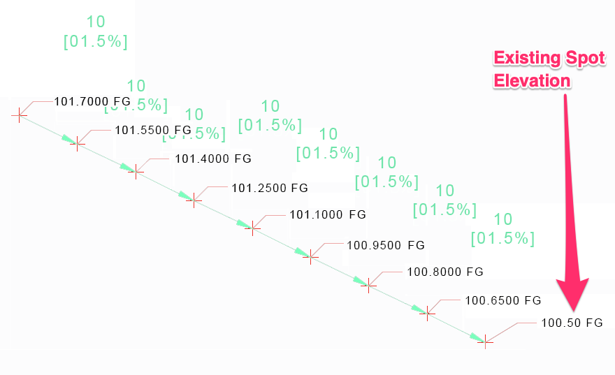
If you want to set an exact spacing pattern for the Spot Elevation callouts you place along the line, check the Place Spot Elevations every option. You can then enter a spacing pattern (example: 10 ft.) and select whether you want the distance to be measured horizontally or vertically.

Here's an example of a line of Spot Elevation callouts placed relative to an existing one:
Polyline
If you place a Spot Elevation near the end of a polyline, you can continue this Spot Elevation along that polyline. This polyline can be a combination of continuous lines and arcs.

To place Spot Elevations along a polyline in your drawing, type R or C when placing a polyline. Select the existing Spot Elevation callout, then select the Slope follows a polyline option in the Slope dialog box.
If you want to set an exact spacing pattern for the Spot Elevation callouts you place along the polyline, check the Place Spot Elevations every option. You can then enter a spacing pattern (example: 10 ft.) and select whether you want the distance to be measured horizontally or vertically.

Use the pickbox to select the polyline.
The Spot Elevations will be filled in.

Placing One Callout With Multiple Elevations
The Spot Elevation dialog box allows you to add elevations for up to three points. You may want to place a single callout showing multiple elevations in several situations, including:
- Top / bottom of wall or curb
- Rim elevations and inverts for catch basins or manholes
- Finish grade vs. soil grade

To place a single callout showing multiple elevations, enter the elevations in the Point 1, Point 2, and Point 3 text fields, with the highest elevation at Point 1. If only adding two elevations, use the Point 1 and Point 2 fields.
In our example, we'll enter a top-of-wall elevation of 253.00 in the Point 1 field with an abbreviation of TW, and a bottom-of-wall elevation of 252.49 in the Point 2 field with an abbreviation of BW.
In our example, the resulting Spot Elevation callout would look like this:

Working With Spot Elevation Callouts in the Civil and Survey Manager
After placing some Spot Elevation callouts, you can manage them within the Civil and Survey Manager. You can also place Spot Elevation Callouts directly from the Civil and Survey Manager.
Open the Civil and Survey Manager:
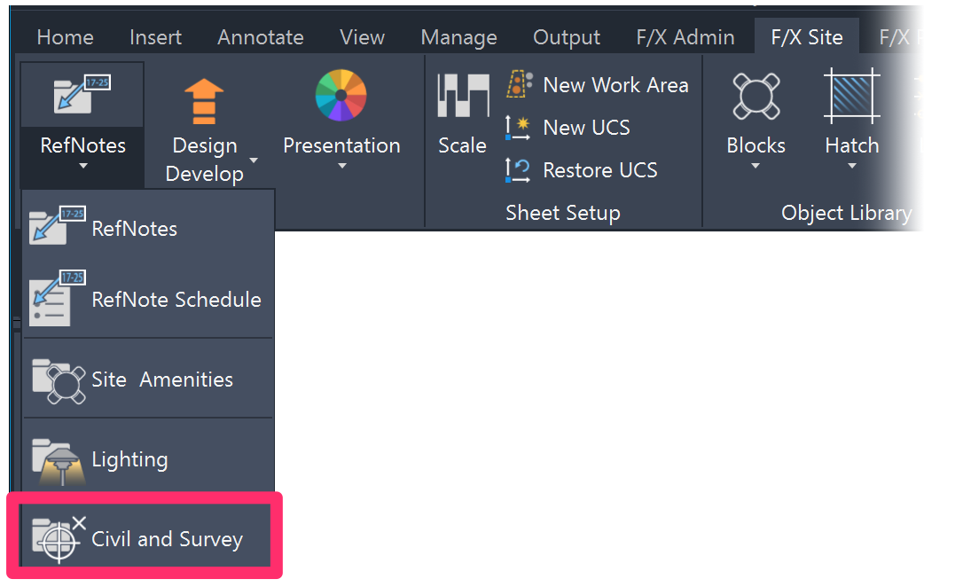
F/X Site ribbon, Civil and Survey flyout
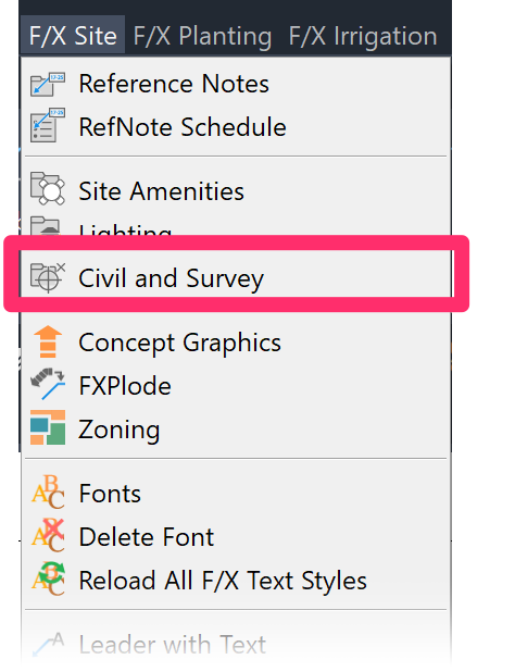
F/X Site menu, Civil and Survey option
or type FX_CIVILSURVEYMANAGER in the Command line
The Civil and Survey Manager is now a docked palette. Want to undock this palette? See our documentation on docking and undocking palettes such as the Civil and Survey, Irrigation, and Plant managers.

1. Select the Spot Elevations tab.
2. List of Spot Elevation callouts you've placed in your drawing.
3. Refresh button to refresh the list of Spot Elevation callouts to show changes you've made.
4. Delete a Spot Elevation callout from the list.
5. Locate a Spot Elevation callout in your drawing by selecting it in the list and clicking this button. Your drawing will zoom to the callout where it's been placed.
6. Place a Spot Elevation callout in your drawing.
7. Place a Spot Elevation Schedule. More information
Spot Elevation Schedule
With the Spot Elevations option selected in the Civil and Survey Manager, click Schedule to place a Spot Elevation Schedule.
The Spot Elevation Schedule is now powered by our Reference Notes (RefNotes) Schedule feature, which we improved with some major updates as of August 2024. More information


Select a destination for the schedule:
- Table: Place the schedule in your drawing as a table.
- Gridlines non-plot: Check this option if you want the lines separating the table cells to be non-plot. Uncheck this option if you want the table lines to plot.
- Spreadsheet: Export the schedule to a spreadsheet program such as MS Excel.
We've replaced the Drawing and Table options with this single Table option and the Gridlines non-plot checkbox. If you select Gridlines non-plot, the schedule will place with gray gridlines that will not show up when you plot your drawing (essentially the same as the former Drawing option). Deselecting this option will result in a schedule placing as a table with gridlines set to plot (essentially the same as the original Table option). This updated system allows you to edit your schedules much more easily.
Click OK to place the schedule.
If you selected the Table option, the Command line will prompt: Upper Left Corner.
Click to place your Spot Elevation Schedule. The schedule will include columns for Abbreviation, Elevation, Northing coordinate, and Easting coordinate for each Spot Elevation callout.
Here's an example of a Spot Elevation Schedule:

Assigning a Z Elevation to a Spot Elevation (Spot Elevation Z Align)
Need to coordinate with Civil 3D, a surveyor, or with a 3D modeling program like SketchUp, Rhino, or Revit? We've added the ability to assign a Z elevation to each Spot Elevation callout with our Spot Elevation Z Align tool. See our Spot Elevation Z Align documentation for details and instructions.
Slope Callouts
Slope Callouts show the direction and percentage of slopes in your drawing. For more information, see our Slope Callouts documentation page.

When calculating a slope, note that if you select a Spot Elevation callout that lists multiple elevations, the system will use the Point 1 elevation for the calculation.
Related Webinars
- Simple Site Layout and Grading Tools: Our Civil and Survey Manager (formerly known as the Grading Manager) includes some easy-to-use tools designed to help you lay out a plan in AutoCAD with Northing/Easting points, Spot Elevations, and Slope Callouts. We'll go over a few basic examples showing how these tools work, and provide some tips on how to incorporate them into your construction documentation workflow. (58 min)
- Grading A, B, C for Landscape Architects: Follow along as we cover the basics of simple landscape grading. We cover some simple concepts like calculating slope and interpolating contours, and show you how to use our easy grading tools in a real plan. (1 hr 4 min)
- Common Land F/X Questions: This webinar covers some of our lesser-known tools, including our Spot Elevation tool and how it relates to Slope Callouts. (1 hr)
- Grading and Drainage: Learn simple grading processes using our annotation tools, as well as some basics in Civil 3D for more dynamic site modeling. We'll explore how to automate your grading workflow based on the needs of the project. (1 hr 2 min)
- Site Plans and Land F/X: Aaron Emerson of Mills Design Group will show some award-winning case studies of how the Land F/X Site tools, including the grading tools, are used throughout his office. Aaron will also go over some important lessons learned while setting up an efficient site design workflow. (57 min)
Troubleshooting
Issue: Spot Elevations and/or Slope Callouts are oriented incorrectly or pointing in the wrong direction
Issue: You saw an "Invalid input" message in the Command line when placing Spot Elevation callouts