
Discipline Graphics
Updated on: November 24, 2025
Quick video

- Discipline Graphics Overview
- Callouts
- Area Callouts
- Breakline
- Northing / Easting Points
- Match Line
- Revision
- Section Callouts
- Sheet Callout
- Slope Callout
- Spot Elevation
- Viewpoint
- Arrows
- North / Scale
- Civil
- Electrical
- Keyboard Commands for Placing Discipline Graphics
- Saving Your Own Discipline Graphics in the User-Defined Folder
- Saving Your Blocks as Discipline Graphics
- Creating & Saving Discipline Graphic Blocks With Attributes
- Accessing Your Discipline Graphics
- Editing Blocks in the Discipline Graphics Library
- Assigning Data to Discipline Graphics You've Already Placed
- Rescaling Discipline Graphics
- Related Webinars
- Troubleshooting

Landscape architects often need to access standardized symbols that are not simply specific to landscape architecture. These symbols may apply to other disciplines, such as civil or electrical.
Our Discipline Graphics libraries are convenient locations where you can file miscellaneous drawing blocks that relate to other disciplines.
Discipline Graphics Overview
Open our Discipline Graphics tool:
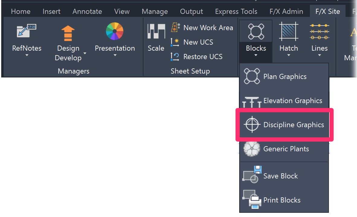
F/X Site ribbon, Discipline Graphics flyout

F/X Details ribbon, Discipline Graphics button
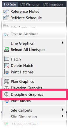
F/X Site menu, Discipline Graphics option
or type DisciplineGraphics in the Command line
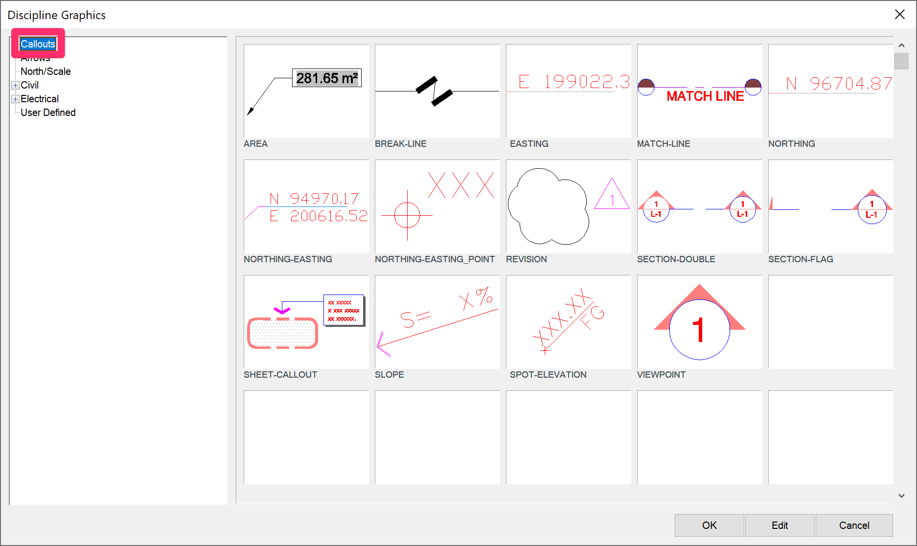
The Discipline Graphics dialog box will open.

1. The left pane of the dialog box shows the Discipline Graphics library categories. Click the plus (+) sign next to a category to expand it and show its subcategories.
2. Click one of the subcategories to select it and show the Discipline Graphics it contains.
3. The Discipline Graphics within the selected subcategory appear as thumbnails in the area on the right side of the dialog box. Click a thumbnail to select the corresponding Discipline Graphic. Click OK to place it in your drawing.
4. Click Edit to view and change information about the selected Discipline Graphic.
In addition to two specific disciplines of Civil and Electrical, the Discipline Graphics folders include Callouts, Arrows, North/Scale, and User-Defined.
Callouts
Callouts are a variety of miscellaneous graphics and features used for general construction document preparation.
You can also open our library of site callouts by clicking the Callouts flyout on the F/X Site ribbon.

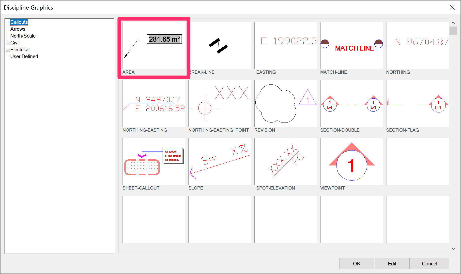
Area Callouts
Quick video
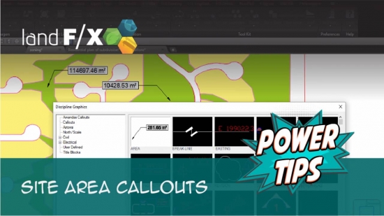
With this tool, you can call out the area of an object in your drawing. You can also access Area callouts by typing FX_AreaCallout in the Command line.
After selecting Area Callout, select a closed polyline or hatch. A multileader (MLeader) callout will appear, displaying the area of the object you selected.
If you adjust the size of the object you've called out, type REGEN in the Command line and press Enter. The area total will update.
Note that you can also double-click on the text to add text to the original MText edit box. You can also right-click on the callout to add or remove leaders.
Breakline
Breakline is a quick way to insert a break for a line defining a continuation of an object.

Draw a line with an appropriate layer to separate the continuation of some object. Select Break Line, and use the pickbox to select the separator line.
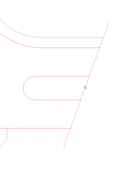
Use the pickbox to select the location on the separator line where you want a break.

A line break is inserted at that location.

Resultant plot.
Breakline is useful on both plans and details.
Northing / Easting Points
The Callouts library contains several options for Northing/Easting Points.

These options will place the distance in either Northing-Easting, or just Northing or Easting, from the insertion point 0,0 of the drawing to the location selected. The 0,0 insertion point of the CAD file should be a known survey point or benchmark that can be measured from in the field.
For more information, see our Northing/Easting Points documentation.
Match Line

The Match Line feature allows you to place a Match Line callout within a drawing. A Match Line indicates where a larger site is broken into smaller visible areas so that each area can be defined on a sheet.
Click where you want the first "circle" to define the Match Line, then click the second location. A line will be drawn between the two, and you can decide the “viewing” direction (a filled-in portion of half of the circle). You would then type the title of the Match Line.

Typically, the filled portion of the Match Line callout indicates the side of the Match Line that is defined in the current drawing.
Revision
The Revision tool will quickly place a revision cloud and a revision triangle where you enter the number.

Select Revision. The Command line will prompt you to Specify start point or [Arc length] Object style] <Object>.
Click to select a start point for the revision graphic. When you move the mouse, a revision cloud will appear.
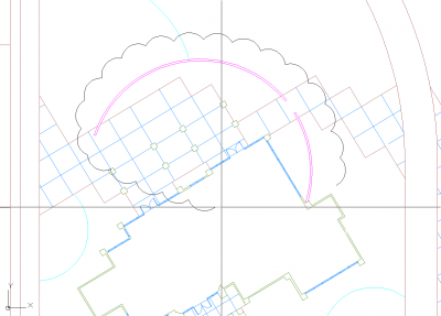
Move the mouse to define the revision cloud line.

When the line closes, locate the revision triangle.
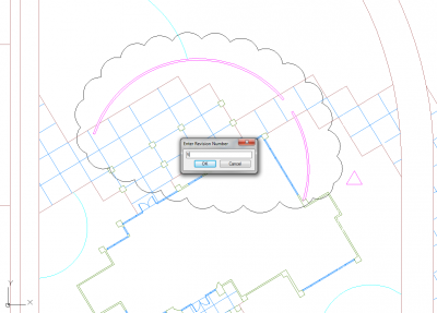
When you locate the revision triangle, enter the revision number.
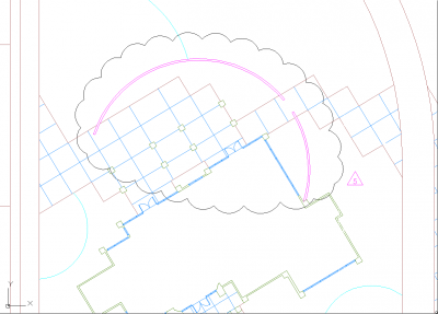
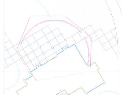
The finished product
- When placing the revision triangle, you can right-click to exit that placement and just place the revision cloud.
- The layer of the revision cloud is L-ANNO-LABL, and the color can be changed to suit your plot needs either manually in the CAD Layer Properties Manager. Alternately, you can adjust that layer color permanently using the General Preferences screen.
Section Callouts
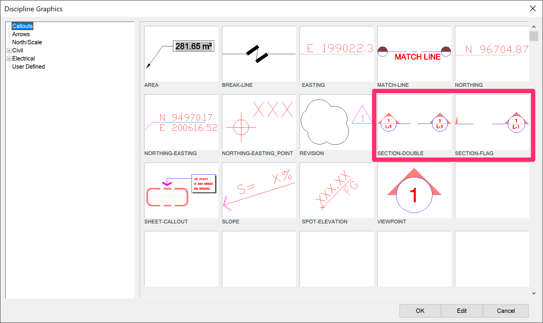
These graphics allow for the manual placement of a section flag or a double section callout. This is similar to the same features within our collection of Detail Callouts, but the detail number and sheet number are placed manually.

The Section Flag and Double Section Callout examples
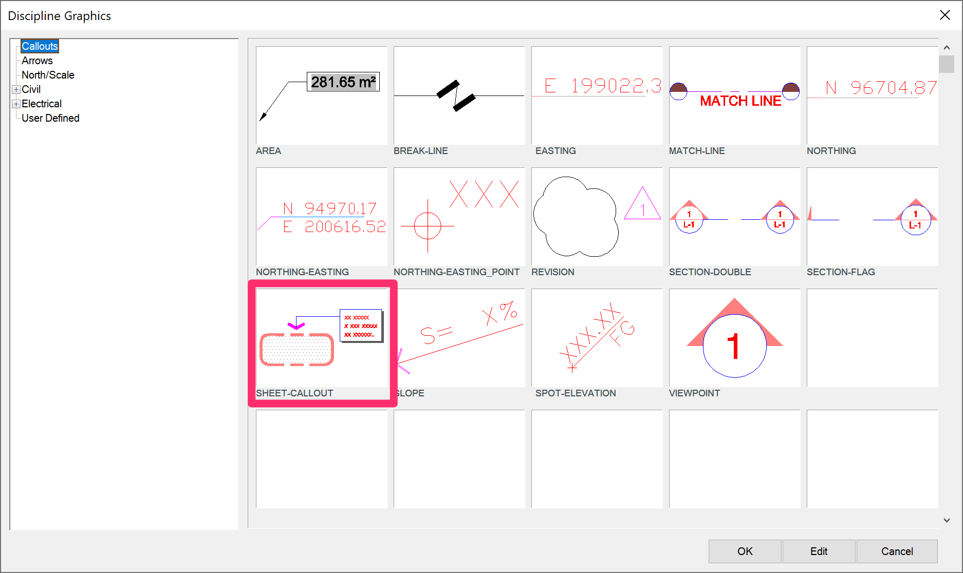
Sheet Callout
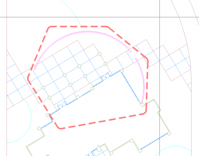
While this tool is called Sheet Callout, it could have many types of uses. The intent of the tool is to place a border and a shading around a defined area and then indicate what this area represents using text that is boxed with a drop shadow.
Typically, you might indicate in the text: "Detail blowup area, see sheet L401" or something similar. The text does not necessarily have to relate to a certain sheet, but could indicate something like "Area for Phase 2 work."
When you select Sheet Callout, the Command line will prompt: First point, [Select]
At this point, you can either:
- Start to define the boundary by clicking points in your drawing or ...
- Type S to select an existing polyline.
Draw the boundary, and right-click when you want to end the function and close the boundary line. You will be prompted to place a leader arrowhead at the bounding line. You can then define text with multi-line or single-line text. The text will receive a boxed look with a drop shadow, and the defined area will be filled with a screen hatch pattern of dots.
Select points to define where the boundary is located, or type S to select an existing polyline.
Right-click to end the function and draw the boundary.

Click where you want the leader arrow to connect to the boundary, and define the leader.

Right-click for multiline text (M-text), then type the text the text. Click OK in the M-text dialog box when finished.
The best way to enter text is with multi-line text (MText), so right-click to activate Sheet Callout. You can see the text going in, and you'll need to press Enter at the end of each line to define the text breaks.

When you're finished, the text will be boxed with a drop shadow, and the area defined will receive a dot hatch pattern fill.

The plotted result
Slope Callout
Slope Callouts indicate the percentage and direction of slopes in your drawing.
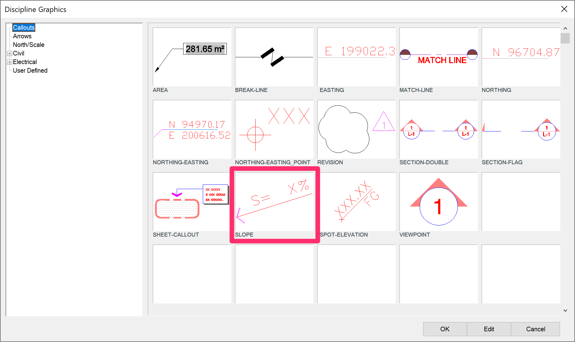
For more information, see our Slope Callout documentation.
Spot Elevation

Spot Elevations are markers of elevation in your drawing. You can place spot elevations onto a plan, as well as determine one spot elevation in relation to another given a slope between the two.
For more information, see our Spot Elevation documentation.
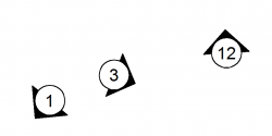
Viewpoint
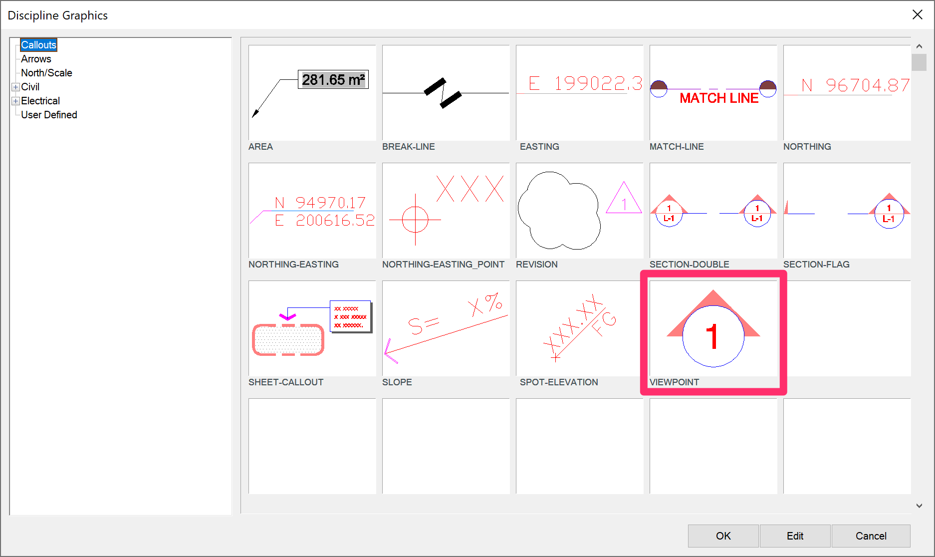
With the Viewpoint tool, you can place a reference to a certain direction. For example, you might place a viewpoint that directs your client to view a certain portion of your drawing.
To place a Viewpoint, click where the symbol is located. Then click its direction, and finally add the one or two numbers or letters that will be in the callout
Arrows
The Arrows Discipline Graphics consist of a number of custom arrow types. Select Arrows in the Discipline Graphics dialog box to view the array of available Arrows.

Click an arrow type to place it in your drawing. When you place the arrow, use the mouse to size it and orient it to a desired direction manually.
Each of these arrows is filled with a solid hatch pattern. If you want to adjust the fill color or density, go to the layer X-SYMB-FILL and adjust it as desired.
North / Scale
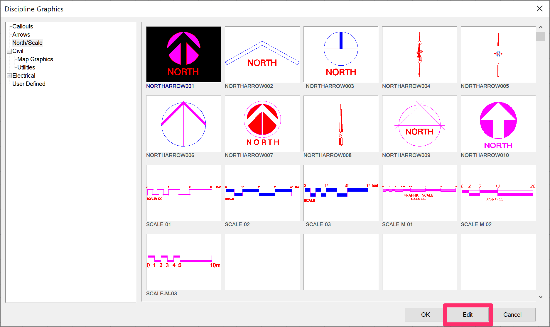
Select North/Scale in the Discipline Graphics dialog box to view the North Arrow and Scale Discipline Graphics. These graphics, intended for use in Paper Space, are most commonly used next to the title of a site drawing view.
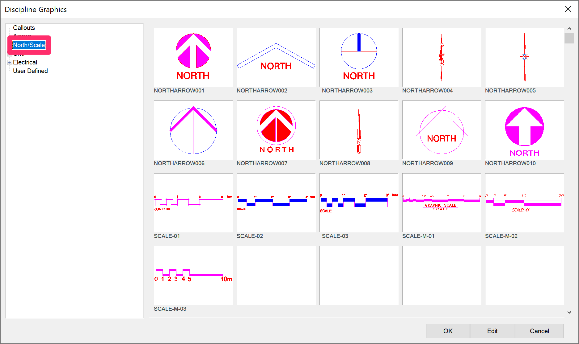
Click a north arrow to place it in your drawing, then use your mouse to scale it manually.
The Scale Bars will be placed and will automatically fill in with the scale you've set. You can also customize your own scale bar with reference numbers tailored for any scale you choose. For more information, see our Customized Scale Bar Block article.
This is an extremely handy graphic location for setting up a drawing sheet.
Civil
Civil graphics are intended to include symbols relating to civil engineering. Selecting the Civil libraries in the Discipline Graphics dialog box accesses the same graphics libraries that open when you select a grading, civil, or survey item using our GradingCivil and Survey tool.
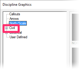
Click the plus (+) sign next to the Civil entry to expand your view of the Civil library

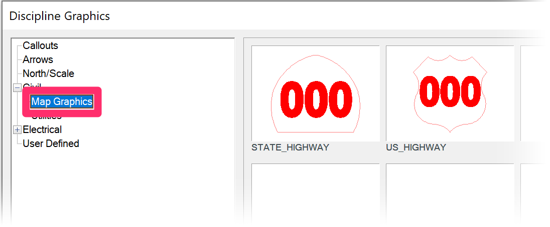
Your default installation provides two Discipline Graphics libraries in the Civil category: Map Graphics and Utilities.
You can add to the existing Civil libraries by using our Save Block tool. You can also add your own libraries, which are simply folders under Civil graphics.
The default Map Graphics library includes State and U.S. Highway markers.
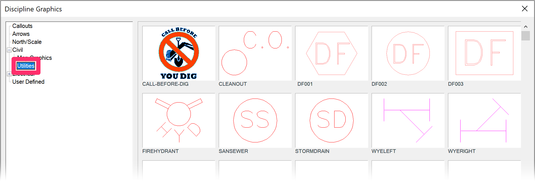
The default Utilities library includes a number of markers for different utilities.
You can add to these libraries or create your own.
This graphic location is also important because it serves as the graphic source for symbols for the Grading tool.
Electrical
Electrical graphics are intended to be miscellaneous symbols that usually relate to the electrical discipline.
Selecting the Electrical libraries in the Discipline Graphics dialog box accesses the same graphics libraries that open when you select a Lighting item.

Click the plus (+) sign next to the Electrical entry to expand your view of the Electrical library.
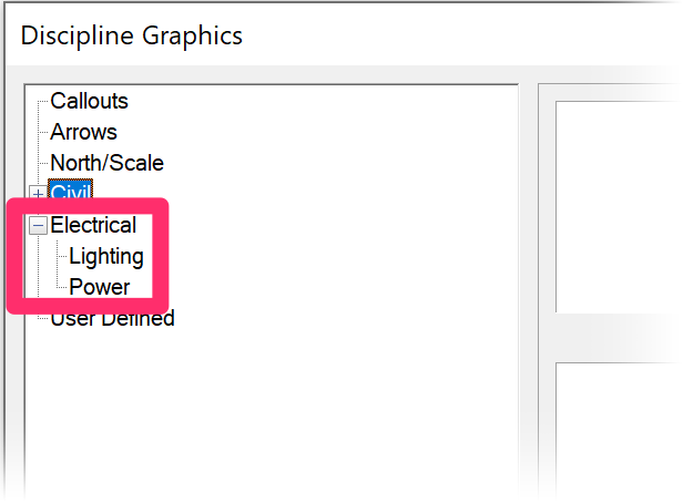
Your default installation provides two Discipline Graphics libraries in the Electrical category: Lighting and Power.
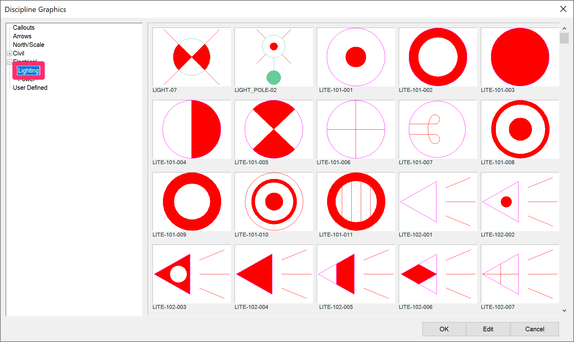
The Lighting library

The Power library
As with the other Discipline Graphics libraries, you can also add your own libraries (which are just folders under Electrical graphics) or add to existing libraries with our Save Block tool.
This graphic location is also important because it serves as the graphic source for symbols for the Lighting tool.
Keyboard Commands for Placing Discipline Graphics
Our keyboard commands for placing objects now apply to generic blocks, such as Discipline Graphics. Use these easy, intuitive keyboard commands to toggle between blocks, block categories, and views of the selected block on the fly, as well as enter our Copy along tools. More information
Saving Your Own Discipline Graphics in the User-Defined Folder
Finally, the Discipline Graphics tool allows you to access User-Defined graphics – miscellaneous blocks and symbols that you add to this library.
Saving Your Blocks as Discipline Graphics
You can save miscellaneous notes, registration stamps, office logo, title block, and any other blocks into the User-Defined subfolder using our Save Block tool. For instructions, see our Save Block documentation page.

When saving Discipline Graphics, save them to either the folder LandFX\blocks\discipline_graphics\95-user_defined or another subfolder you've created in the discipline_graphics folder.
Creating & Saving Discipline Graphic Blocks With Attributes
You can create your own custom Discipline Graphic blocks that include attributes – dynamic text components that can reflect different values each time the block is placed. For instructions, see our Discipline Graphics with Attributes documentation.
Accessing Your Saved Discipline Graphics
To place a Discipline Graphic block you've saved, select the category in the Discipline Graphics dialog box that corresponds with the folder where you saved the block.
You'll see a thumbnail preview for your saved block in the right portion of the dialog box.

Editing Blocks in the Discipline Graphics Library
If a block in the Discipline Graphics library is not scaled correctly or is not set to proper rotation, or if you want to open the block's source file to customize it, select the block's thumbnail preview in the Discipline Graphics dialog box and click Edit to make changes to that block.
You can then view and edit information about the block.

1. Larger preview of the selected block
2. If you want, type a Description for the block.
3. Set a Scale for the block. In this example, the item is set for a Scale of 1:1, meaning it will go into the drawing at full size rather than Dimscale or Manual.
4. The Rotation that will be applied to the block when placed in a drawing.
- In this example, the Rotation is set to No Rotation, meaning the block will be placed into the drawing with no rotation on your part.
- Selecting Manual will allow you to rotate the block to your desired angle when you place it in the drawing.
5. Use this menu to select the Units assigned to the block: Inches, Feet, Meters, etc.
6. Click Edit File to open and edit (customize) the source file for the selected block.
If you change the Units of a block in the Elevation Graphics library and then add the block as a Reference Note, you will then need to change the units in the Reference Note as well.
Assigning Data to Discipline Graphics You've Already Placed
Quick video

What if you've you've already placed several Discipline Graphics in your drawing, but you now want to assign those objects with data (such as cost) and call them out in a materials schedule?
We've engineered a quick and simple way to do just that – by converting them into Amenity (Object) Reference Notes. For instructions, see our Assign Data to Generic Blocks documentation.
Rescaling Discipline Graphics
If the text in your Discipline Graphics is coming in too big or too small in relation to the rest of your drawing, you're most likely facing a scaling issue. If this is the case, follow our steps to correct scale in callouts.
If you want to make permanent changes to the size or scale of one of the Discipline Graphics as it inserts in your drawings, you can do so by editing its source block.
Related Webinars
- Fundamentals of Blocks: Take a tour of the streamlined process for proper block creation and management brought to you by Land F/X. We’ll cover the dos and and don’ts of creating and saving blocks, and demonstrate how our numerous block library locations work with different parts of the software. (1 hr 2 min)
- Working with Blocks: We go over the role played by blocks within our software, showing the various types of blocks you have access to and how they all function. We'll also show you how to integrate your personal set of custom blocks into our system. (51 min)
- Using PDFs to Start Your Designs: We show you how to bring a PDF into your drawing, scale it properly, and turn it into your base files. We'll show off a few of the blocks in our Discipline Graphics library that are especially helpful in this process. (1 hr 3 min)
Troubleshooting
Issue: You are experiencing a significant delay when attempting to add or place Discipline Graphics
Issue: Bad DXF group (10) error when placing a Discipline Graphic
Issue: You saw a Missing File Error when attempting to place a Discipline Graphics block
Issue: Your custom blocks are not showing up as options in the Discipline Graphics dialog box