
Land F/X Block Creation from Scratch: Detailed Instructions
Updated on: March 11, 2026
- Initial Setup
- Layers
- Drawing the Block
- Coloring the Block
- Block Checklist
- Saving
- Block Creation Scenarios
The following steps provide detailed instructions for creating blocks to Land F/X standards for use in the software.
Initial Setup
1. Open a new drawing file in CAD.
2. Set the units.
Use the UNITS command to set units to Architectural Inches or Decimal Millimeters. Whether inches or millimeters, stay consistent as you block out your catalog.

3. Select the Load Layers tool from the F/X Admin ribbon to load the appropriate Layer States.
Select the [BLOCKS] category, then select the _GENERIC_ Layer State,


4. Assign the correct Preference Set to the drawing
Navigate to Preferences and choose the appropriate Preference Set:
- Imperial if drawing in inches, or
- Metric if drawing in millimeters
The drawing will default to the Preference Set at the top of the list.
5. Set the default Save As file format to AutoCAD 2018
Use the OPTIONS command and, under the Open and Save tab, set the Save As format to AutoCAD 2018/LT2018 Drawing (*.dwg).

Layers
Block layer linetype settings.
All standard block layers have names beginning with LK-. This just means Land F/X block.
Following LK- is the 4-letter code representing the block type. If you load the _GENERIC_ layer state, this code will be XXXX. Replace these characters with the appropriate 4-letter block type from the table below.
4-Letter Block Type
FURN
AMEN
STRC
ATHL
POOL
PEOP
ANML
VEHC
ACCS
DRAN
ARCH
Definition
Site furnishings
Site amenities
Site structures
Athletic
Pools/spas
People
Animals
Vehicles
Accessibility
Drainage
Architectural
Examples
Benches, chairs, tables, umbrellas
Trash receptacles, BBQs, bike racks
Gazebos, pergolas, shade structures
Sports fields/courts, athletic equipment
Pools, spas, pool equipment
Sitting, standing, walking, in wheelchairs
Dogs, cats, farm animals, velociraptors
Cars, trucks, boats, public transit
Handicap areas/markers, ramps
Area drains, French drains, catch basins
Appliances, entertainment, sinks, toilets
Following the block type is the layer name suffix:
Layer Name Suffix
-013M
-025M
-NPLT
-PATT
-PATT-60TPY
-PATT-70TPY
-PATT-90TPY
-COLR
Definition
0.13mm lineweight
0.25mm lineweight
Nonplot lines
0.13mm hatch pattern
60% transparency
70% transparency
90% transparency
Solid color fills
Use
Use for interior and detail lines
Use for exterior and lines that need to stand out
Lines that won't plot, great for hatch boundaries
Use for hatches (excluding solid color hatches)
Use for hatches (excluding solid color hatches)
Use for hatches (excluding solid color hatches)
Use for hatches (excluding solid color hatches)
Use for solid color fills (created by site color tool)

Standard _GENERIC_ block layers in the Layer Manager

Generic block layers in CAD

Generic block layers plotted
Drawing the Block
- Use only the Polyline, Circle, Hatch, and Arc tools to draw the block elements at a 1:1 scale.
- Place linework on appropriate layers, as outlined in the Layers section above.


- The insertion point must be at the origin (0,0).
Different types of blocks have different insertion points. For example, a plan-view bench insertion point should be at the back left corner of the bench, while a plan-view table insertion point should be at center-center. Reference the Land F/X generic block library to see where the insertion point should be for the type of block you're creating.
- Draw simple, closed shapes to ease coloring the block.
- Take care to only include enough detail to convey the necessary elements of the block. Keep in mind that a user's plan render will likely be zoomed out much farther than your up-close view of the block while you're creating. A little goes a long way.

Too detailed
Correct level of detail
Coloring the Block
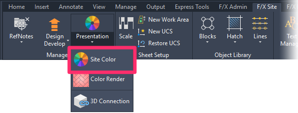
Once linework is complete and the block is positioned and oriented appropriately, add color to the block with the Site Color tool under the F/X Site tab.


Guidelines:
- Set up your color palette. You can make several color wheels, each with 12 colors. Left-click on a color to see 5 shades fly out to the right of the wheel. To edit any of these colors, right-click and select Edit from the menu that opens. Use only True Color.
- The Site Color tool will place color fills on a layer named L-SITE-COLR-FILL.
Important: After placing all the color, take care to rename the L-SITE-COLR-FILL layer to LK-(type)-COLR.
- Use as few hatches as possible to keep the block lightweight efficient. If possible, use a single hatch per color.

4 hatches

1 hatch
- Place the initial color hatch with the Site Color tool, then use the Pick Points function in the Hatch Editor to select the other areas that should be filled with the same color.

- You can Plot Preview intermittently to see how the block will appear when plotted.
Verify that the LFX.ctb option is selected from Plot style table (pen assignments) and the Plot transparency option is enabled.

Block Checklist
Go through the following checklist to ensure you've created the block is correctly:
- No ellipses, splines, text, or dimensions.
- No Xrefs, Proxy Objects (Proxies), DGN linetypes, or Registered Applications (RegApps).
- No groups or blocks.
- Uses only Land F/X standard layers.
- All layer names contain the appropriate 4-letter layer type (not XXXX!)
- All objects' properties set ByLayer (except color fills).
- All objects at 0 elevation.
- Insertion base set to 0,0.
- Insertion point set at the appropriate place on the block.
- Zoom (Z) to Extents (E) to ensure that no extraneous elements are occurring outside the block.
- Model drawn in inches or millimeters at 1:1 scale.
- Layer 0 set to active (once finished).
- -COLR layer visibility turned off (once finished).
- Run the PRG command to ensure that only the layers with content are present.
Saving
Saving Generic Blocks
Once you've completed the block, use the CTRL+A keys to select all objects (including the solid color hatches, which should be on the -COLR layer with visibility turned off), and save using the Save Block tool. This step will generate the necessary DWG, XML, SLD, and/or PNG files. (The SLD or PNG file is the AutoCAD slide – the thumbnail that will appear in the block selection dialog box.)
You'll first be prompted to specify an insertion point. Type 0,0 then press Enter.
You'll then be prompted to specify a folder location and filename. Navigate to the appropriate one of the following locations:
- (C:)\LandFX\Blocks\plan_graphics\99-user-defined
- (C:)\LandFX\Blocks\elevation_graphics\99-user-defined

The file name must match the block name on the Master Block List spreadsheet, and should therefore adhere to the following format: LAFX-XXXX-VV-YYY-ZZZD.dwg
Name Component
XXXX
VV
YYY
ZZZ
D
Definition
Block Type
View
Category
Block Number
Dynamic Block Designator
Brief Description
See the Layers section of this guide.
PV (Plan-View), EF, ER, EB (Elevation Front, Right, or Back)
Category (See Master Block List)
Unique block identifier number.
The letter D, only included if the block is dynamic.

LAFX-FURN-PV-101-006

LAFX-FURN-EF-101-006

LAFX-FURN-ER-101-006
You'll then be shown a preview of the slide (thumbnail) and prompted to enter scaling and rotation settings:
- Scale and Rotation:
- Plan-view blocks should have the Scale set to 1:1 and the Rotation set to Manual.
- Elevation blocks should have Scale set to 1:1 and the Rotation set to No Rotation.
- Leave the Description field blank.
- Click OK to create the files.
After clicking OK, open the XML file for the block and verify that the block_color line item is set to 3.

Saving Manufacturer Product Blocks
Manufacturer product blocks can be saved normally, without using the Save Block tool. (Manufacturer blocks do not use thumbnail slides, and the XML data is created by the system on the fly when the user downloads the block).
The filename should follow the following format: MANU-MODEL_NAME.dwg
MANU represents the 3- or 4-letter manufacturer code.
MODEL_NAME represents the name of the model as it's entered in the database, in ALL CAPS, with any spaces replaced with underscores (_).

Block Creation Scenarios
Scenario 1: Conforming an Existing Block to Land F/X Standards
1. Open a blank new drawing, and complete the Initial Setup steps above.
2. Open the existing DWG. Copy the linework to be used in the block, and paste it into the new drawing. Leave out dimensions and text, as those items would carry over unnecessary styles into the new drawing.
3. Remove ellipses and splines.
- Select all objects, and check the Properties drop-down menu to see which elements are present.
- If ellipses or splines are present, use QUICKSELECT or QS to select them.
- Object type: Ellipse or Spline.
- Operator: Select All.
- OK.
- Move splines and ellipses to a "Temporary" layer.
- Use polylines to trace over splines and ellipses on the correct layer.
- Delete the "Temporary" layer using the LAYDEL command.
Alternatively, ellipses can be converted to polylines using the EL2PL.lsp LISP routine.
Splines can be converted to polylines using the PEDIT command. However, PEDIT will not delete the splines automatically when it creates the polylines. Take care to delete the splines afterward.
4. Clean the rest of the drawing to satisfy the requirements in the Block Checklist.
Scenario 2: Creating a Block from Scratch Using a Plan View Image, a SketchUp file, or Spec Information
Plan View Image
Some spec sheets will contain a plan-view detail drawing of the product. This is a great option because we can just trace the product in CAD.
1. Use the screenshot tool (Command+Ctrl+Shift+4 on Mac) to capture an image of the detail.
2. Use the IMAGEATTACH command to attach the image.
3. Resize the image to match the actual product dimensions. You can do so by drawing a line at a known dimension and using the ALIGN command.
4. Change the transparency of the image to 50 in the Properties, and trace over it with polylines.
SketchUp File
If we don't have an image to trace but do have a SketchUp file, we can generate a 2D DWG file from SketchUp. To do so, open the SKP file and set up the model as follows:
- Camera>Standard Views>Top Camera>Parallel Projection File>Export>2D Graphic
- The SketchUp-generated DWG will likely have extraneous linework to remove.
Spec Information
If we have no image to trace or DWG files, we'll need to create the blocks based on the dimensions/specifications of the spec.