
Modifying Updated Valve Callouts
Updated on: March 10, 2026
- Anatomy and General Rules
- The Do's and Don'ts of Valve Callout Dynamic Blocks
- Adding Attributes to Valve Callout Dynamic Blocks
- Customizing Valve Callouts So Text Appears After Attributes
- Updated Valve Callout Background Masks
Our updated Valve Callout tool now places valve callouts as complete dynamic blocks. As with our 2025 update to our Detail Callouts, these blocks act more like multileaders (Mleaders) to offer better functionality during and after the callout blocks are placed. Otherwise, the updated valve callouts will act and place as they did previously.
Such an advanced dynamic block is quite delicate, however. Some features can be customized, and some can't, but even for customizable features, you'll need to take extreme caution to avoid breaking the dynamic parameter links and causing the callout to function incorrectly.
Broken callout behavior includes:
- Issues with attribute text, including:
- Placing in the incorrect position relative to the rest of the callout.
- Not flipping either left or right when the callout is flipped.
- Not moving with the rest of the block when the block is moved after initial placement
- Missing or filled out incorrectly.
- The scale of certain elements of the callout is incorrect.
- Arrow not moving correctly or disassociated from the grip.
- Missing grips.
- Block not placed in the correct orientation (right or left) after being placed.
Anatomy and General Rules
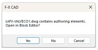
When you open one of the updated LAFX-VALVECO source blocks in the folder LandFX\Blocks\Graphics\Irrigation\Callouts, you'll be asked whether you want to open the file in the Block Editor. Always click Yes.
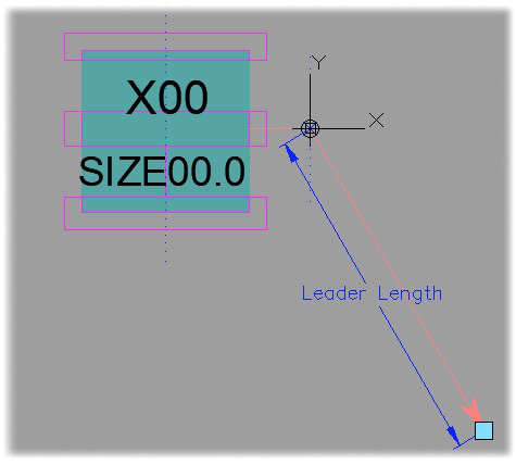
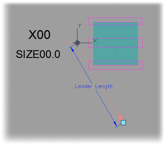
Here are examples of the callout style LAFX-VALVECO1 with and without a leader:

LAFX-VALVECO1 (with leader)

LAFX-VALVECO1X (without leader)
Valve Callout Block and Sub-Block File Names
The names of the source files for the dynamic valve callout blocks start with the characters LAFX-VALVECO. Each callout style has separate primary source block files for the following uses:
- Imperial callout with leader (example: LAFX-VALVECO1)
- Imperial callout without leader, with a file name ending in X (example: LAFX-VALVECO1X)
- Metric callout with leader, with a file name ending in -M (example: LAFX-VALVECO1-M)
- Metric callout without leader, with a file name ending in X-M (example: LAFX-VALVECO1X-M)
If you want to customize any of these callout styles (dynamic blocks), you'll also need to edit the sub-blocks corresponding to the left and right versions of that callout style. The names of these left and right sub-blocks contain the characters -L and -R respectively. Note that the versions of each callout style with and without a leader use the same -L and -R sub-blocks, so you'll only need to edit one set of sub-blocks for each callout style. For example:
- Customizing either the callout style LAFX-VALVECO1 (Imperial callout with leader) or LAFX-VALVECO1X (Imperial callout without leader) will require you to edit the following sub-blocks:
- LAFX-VALVECO1-L (sub-block for the left callout)
- LAFX-VALVECO1-R (sub-block for the right callout)
- Customizing either the callout style LAFX-VALVECO1-M (Metric callout with leader) or LAFX-VALVECO1X-M (Metric callout without leader) will require you to edit the following sub-blocks:
- LAFX-VALVECO1S-M-L (sub-block for the left callout)
- LAFX-VALVECO1S-M-R (sub-block for the right callout)
Note on customizing the metric callouts
Note that this update created a native size for the metric callout with this update, which required a new unique sub-block for within these metric callouts. If you've customized the earlier versions of the metric callouts, you'll need to apply your changes to the new -L (left) and -R (right) sub-blocks of these callouts as well.
The Do's and Don'ts of Valve Callout Dynamic Blocks
Don't: Click No when prompted to open in Block Editor, and save the file. This will result in the loss of dynamic functionality.
Do: Always click Yes when prompted to open in Block Editor when opening the DWG file.
Don't: Move, copy, add, or subtract any objects or elements to these blocks. Doing so may result in a callout that has objects and/or elements that lack functionality or mobility, unlike the rest of the block. Need to add attributes? Here's how.
Do: Edit layer names and or colors of existing elements. Editing these elements of a callout does not affect the actions or parameters within the dynamic block.
Don't: Edit the geometry, scale, or size of the actual callouts in the dynamic block DWG. Editing these aspects of the callout in the dynamic block can unlink it or move it out of reach of the dynamic parameters and actions. See our documentation on customizing valve callouts.
Do: Edit actual callouts in the associated sub-block files.
Once you've made changes in the sub-block, you'll need to update the block definition by using our Redefine Block tool on both the -L and -R subblocks within the primary dynamic block to reflect the changes.
Adding Attributes to Valve Callout Dynamic Blocks
Complete the following steps if you need more than the existing 3 allotted attributes (Valve Flow GPM - 00.0),(Valve Number - X00), (Valve Size - Size).
In previous versions, you'd edit the sub-blocks for each callout to add attributes. With the updated dynamic blocks, you'll need to edit both dynamic blocks (LAFX-VALVECO#.dwg and LAFX-VALVECO#X.dwg) for each required valve callout.
1. Open either the LAFX-VALVECO#.dwg or LAFX-VALVECO#X.dwg files you want to edit.
When prompted, click Yes to open the block in the Block Editor.


2. Select an existing attribute to copy.
In this example, we'll choose the attribute Valve Flow GPM - 00.0 attribute.
3. Copy and move the attribute to your desired location.
4. Rename the attribute according to our list of available attributes for valve callouts. In this example, we'll choose the attribute TYPE.

Do your standards call for the text to follow the attributes in your valve callouts? See the steps below on customizing valve callouts so text appears after attributes.
5. Select the words Flip - Attributes under Attribute Flip, then right-click.


6. Hover over the Action Selection Set on the menu that opens, then click Modify Selection Set in the sub-menu .
7. Select any new attributes you need to add, then press Enter. The new attributes will be linked to the Flip - Justification action.
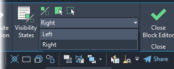
8. In the top right corner of your screen is a drop-down menu in the Visibility tab. It should default to Left.
Open the menu, and select the Right option, as you will now edit the right-facing part of the dynamic block.


9. Note that the new attribute is missing from the Right visibility. To get it to populate, click the Visibility Mode icon, which will allow the new attribute to show.
10. Above the Visibility menu, select the middle icon, Make Visible, then select the new attribute.
The attribute will now be linked to the Right Visibility.

11. Close the Block Editor, and click Save.
12. Repeat steps 1–11 with the LAFX-VALVECO#X.dwg
Customizing Valve Callouts So Text Appears After Attributes
We've seen few Land F/X users' standards that call for having a combination of text and attributes in the valve callouts where the text comes after the attributes, as pictured to the right. The following steps show how to accomplish this look.

The following steps are specific to having a combination of text and attributes where you need the text to always be positioned after the attribute.
All linework customization for the following steps should happen within the source sub-blocks (ex: VALVECO-L & VALVECO-R.
1. After making changes to the sub-blocks (L & R), open the source dynamic callout (example: VALVECO.dwg) and click Yes to open the callout in the Block Editor.
2. Use our Redefine Block tool on both the left and right sub-blocks to ensure latest changes of the L & R blocks are defined in the drawing.

3. Make the needed copies and adjustments of the attributes you wish to show, and verify that the Lock Position setting is set to Yes in the Properties panel for all new attributes.
4. Add a new flip parameter, and place it between the attribute and text you wish to keep in the current order.


Placing the flip parameter in this location will allow the attribute to fill out, keep the describing word of the attribute value constant, and maintain the current order of attribute and text in the placed callout.
5. Select the parameter.
Change the number of grips from 1 to 0, then rename the parameter to Flip Attributes.


6. Assign a Flip Action to the newly placed Flip Parameter, then select all attributes and text objects you wish to keep in that order.

7. Double-click the Flip-Lookup action. Click Add Properties, then select Flip Attributes in the Add Parameter Properties.


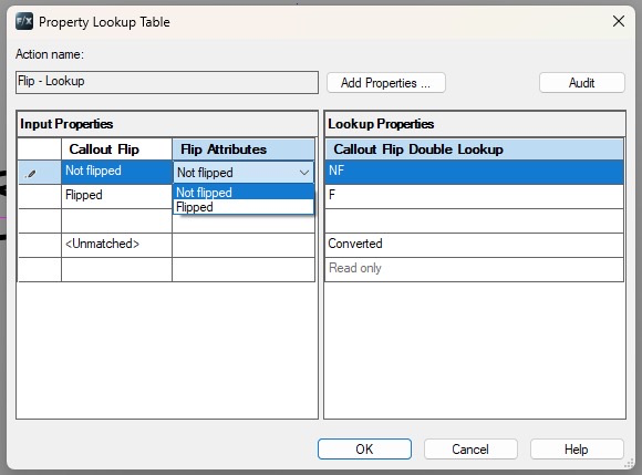
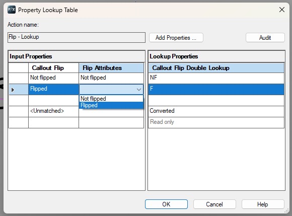
8. Set the flip attributes to match the Callout flip field in the Property Lookup Table.
9. Right-click the Flip - Callout action. Hover the cursor on Action Selection Set in the menu that opens, then select Modify Selection Set in the submenu that opens.
Then select the Flip Attributes parameter and press Enter.


10. Click the Test Block ribbon button to test your changes. Check to ensure the text and attribute(s) are moving and flipping as desired.

11. Save and close your callout file. Repeat these steps in the X version of the callout you just customized (example: if you changed VALVECO5.dwg, then also change VALVECO5X.dwg).
Updated Valve Callout Background Masks
The new valve callout sub-blocks now include the following two background masks:
- LK-IRRG-VALV-MASK: Intended for standard mask purposes.
- LK-IRRG-COLR: Intended for use in conjunction with our Colorize Zones tool.
The colorization mask color properties must remain set to color ByBlock for the mask to function properly.