
Land F/X Detail Creation from Scratch: Detailed Instructions
Updated on: March 30, 2026
- Creating a New Landscape Detail
- Setup
- Drawing the Detail
- Placing the Detail Template
- Hatches and Annotations
- Saving the Detail
- Final Steps
- Creating an Architectural Detail
- Optimizing Details for Land F/X
- Converting Imperial to Metric
- Converting Imperial to Metric: Setup
- Converting Imperial to Metric: Import the Linework and Place a Template
- Converting Imperial to Metric: Annotations
- Detail Creation Checklist
The following steps provide detailed instructions for creating details to Land F/X standards for use in the software.
Creating a New Landscape Detail
- Creating a New Landscape Detail: Setup
- Drawing the Detail
- Placing the Detail Template
- Hatches and Annotations
- Saving the Detail
- Final Steps
This guide is for creating a detail with Imperial units. When completed, the detail needs to be converted to Metric units. For instructions, see Converting Imperial to Metric below.
Creating a New Landscape Detail: Setup
1. Open a new drawing file in AutoCAD.
2. Set the units.
Use the UNITS command to set units to Architectural Inches.

3. Select the Load Layers tool from the F/X Admin ribbon to load the appropriate Layer States.
Select the [DETAILS] category, then select the Landscape Architecture Layer State.


4. Assign the proper Preference Set to the drawing.
Restore the default Preference Set (Imperial or Metric, depending on the units of the detail) from the following location:
/Volumes/GoogleDrive/Shared drives/Content Team/Default Settings - Preference Sets/Default Pref Sets
How to restore a Preference Set
Once restored, open the Preferences or the Project Manager and assign that Preference Set to the drawing. Note that a new drawing will default to the Preference Set at the top of the list (organized alphabetically), so you'll need to verify this with any new drawing.

Drawing the Detail
1. Create the linework for the detail at full size.
Use the Polyline, Circle, and Arc tools to draw the linework within the detail. If the detail is to have an accurate scale, draw everything at full size or a scale of 1:1. No additional scaling necessary.
Do not set the Plot Scale to 1:1. In fact, you shouldn't set the Plot Scale at all for details.
We have a library of blocks specifically for creating details. Access this library by clicking the Details button on the F/X Details, Graphics flyout. Feel free to use these typical components for the detail.


Do not place any hatches or annotations at this stage. You'll place these items only after placing the Detail Template.
It's important to draw the detail in a standard or basic form of installation and, if applicable, show how it fits in the surrounding environment.
2. Place all linework on the appropriate layers. Use the following layers as needed, and purge the rest before saving.
Detail layer linetype settings:
- L-ANNO-LEDR-025M: MLeaders and Bubble Callouts
- L-ANNO-LEDR-035M: Line-wide leaders
- L-ANNO-LEDR-HEAD-025M
- L-ANNO-LEDR-HEAD-035M
- L-BRDR-ENLG: Enlargement border
- L-BRDR-THIN: Enlargement border for thin lines
- L-DETL-013M: 13 mm lineweight
- L-DETL-025M: 25 mm lineweight
- L-DETL-035M: 35 mm lineweight
- L-DETL-050M: 50 mm lineweight
- L-DETL-070M: 70 mm lineweight
- L-DETL-100M: 0 mm lineweight
- L-DETL-ANNO-DIMS: Holds all dimension
- L-DETL-ANNO-TEXT: Holds all MTEXT objects
- L-DETL-BLKS: Bubble Callout blocks
- L-DETL-CNTR: Dashed center line
- L-DETL-GRID: 13 mm lineweight for grid placement
- L-DETL-HIDD-013M: 13 mm hidden line
- L-DETL-HIDD-025M: 25 mm hidden line
- L-DETL-HIDD-035M: 35 mm hidden line
- L-DETL-NPLT: Non-plot lines
- L-DETL-PATT-013M: 13 mm hatch pattern layer
- L-DETL-PATT-025M: 25 mm hatch pattern layer
- L-DETL-RBAR-ELEV: Elevation rebar layer
- L-DETL-RBAR-SECT: Section rebar layer
- L-DETL-REBAR-WWF: WWF rebar layer
- L-DETL-TEXT-025M: Detail text layer
- LK-ANNO-LABL-035M: Label text at 35 mm
- LK-ANNO-LABL-050M: Label text at 50 mm
- LK-ANNO-LABL-TEXT: Bubble Callout label text
Placing the Detail Template
1. Open the Detail Template tool by clicking the Templates button on the F/X Details ribbon.


2. Choose a detail size.
The basic Detail Template size is 1A. This size should be applicable to the vast majority of your details. As the unique needs of certain details dictate, you can select a different template size, such as:
- 2A, 3A, 4A for wider details
- 1B, 1C, 1D for taller details
- 2B, 3C, etc. for taller and wider details
The actual size of this template at 1A is customizable in the Preference Set. By default, it is set to 7.25 inches wide by 7.125 inches in height. All details produced for Land F/X need to adhere to this default setting.
If you already know the scale for the detail, choose that scale and click OK. If not, you can figure out the appropriate scale while placing the template.
3. Place the appropriate detail template around the detail, keeping the following in mind:
- Use the Q and E keys to quickly switch scales while placing the template.
- The A, W, S, and D keys will change the size of the template without changing the scale.
- Take care to leave ample room for annotations.

Hatches and Annotations
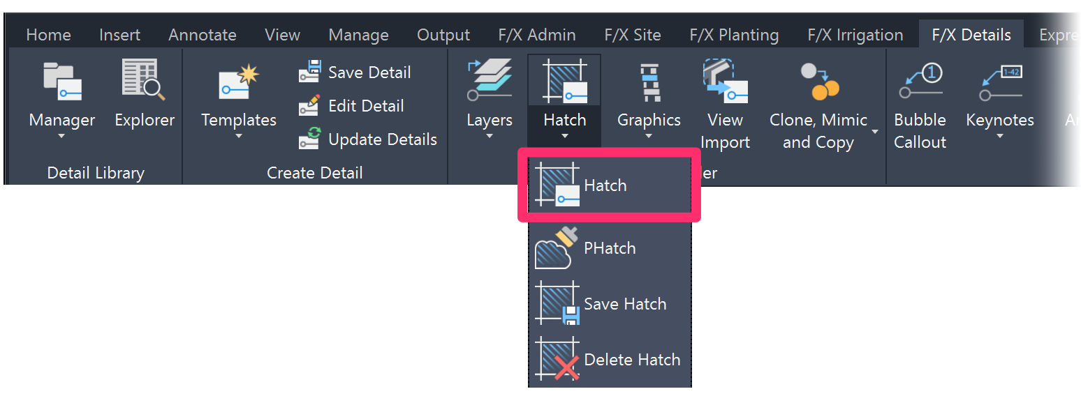
1. Open the Detail Hatch tool by clicking the Hatch button on the F/X Details ribbon.
2. Place the appropriate Land F/X detail hatches into the detail. If the scale is not optimal upon placing, select the hatch and adjust the hatch scale manually.

3. Annotate and dimension the detail, keeping the following in mind:
- All annotations, callouts, and dimensioning should be created using the tools provided within the F/X Details ribbon.
- Bubble Callouts are the preferred tool for labeling detail components. However, annotated leaders are allowed if necessary.
- If using a dimension with text as an annotation, change the DIMENSION TEXT Text Style to DETAIL TEXT. More information about Land F/X Text Styles
- Do not edit the DETAIL-TITLE text. This text will update automatically when the detail is saved.
- Important: Make sure all hatches and annotations are placed on the correct layers!
Saving the Detail
1. Open the Save Details tool by clicking the Save Details button on the F/X Details ribbon.

2. The Select Detail Number dialog box will open.
Browse to and select the folder where you want to save this detail, then click Select.


3. The Save Detail dialog box will open. Give the detail a title and enter the 6-digit CSI number in the Description/Notes section.
The other options are not necessary for saving the detail, but you can also give the file date and drawing credit as needed.
Important! To be able to save details into the F/X Detail Library, you'll need to be signed in to the Content Creation Support ID. If you do not have access to this Support ID, do not save details into the F/X Detail Library, as they will be erased. Instead, save to a custom subfolder.
Move a copy of the detail for review to the following location: Shared drives/Content Team/Details/For Review
Once you've completed the Imperial detail, you'll need to convert a copy of that detail to Metric units. For information on converting to Metric, see Converting Imperial to Metric below.
Final Steps
For the reviewer only:
After the details have been reviewed, they must be saved to S3, prepared for the Land F/X Content Binder, and recorded in the Master Detail List sheet.
1. Save approved details to S3.
- Change Support ID to LANDFX - CONTENT (LIVE).
- Carefully save the details to the appropriate folder location within the F/X Detail Library (FX)
- When finished, switch the Support ID back to the Land F/X Support ID.
2. Add the details to the Land F/X Content Binder.
This step can be as simple as printing the detail as a PDF and submitting the PDF to Forrestt. (Will know more about this soon.)
3. Update the Master Detail List.
- Open the list found in the following Google Drive location: Shared drives/Content Team/Details/Master Detail List.gsheet
- Record the name of the detail in the appropriate location. Add it to both the Master Inventory and to the F/X Standard or MFRS section.
- A Metric version should be already made, so enter Yes in the Metric column.
- Enter Yes in the Content Binder column.
4. Add the news of the details to the upcoming newsletter for announcement. (More on this soon.)

Creating an Architectural Detail
Architectural details are set up mostly the same as landscape details, with a few important changes to the procedure.
• Layer settings
First, when loading the Layer States for architectural details, select the [DETAILS] category, then select the Architecture Layer State.

The names of all layers used in creating architectural details should begin with the prefix A- for architecture.

• Preference Set & Detail Template
Additionally, you'll need to use a unique Preference Set and detail template drawing. Using these items is especially important in keeping your details compatible with the Revit connection.
1. Restore the ArchDetlImp Preference Set (For Imperial units) from the following location:
/Volumes/GoogleDrive/Shared drives/Content Team/Default Settings - Preference Sets/Default Pref Sets
How to restore a Preference Set
2. Copy the detail template drawing file LAFX-DETL-028.dwg into the folder LandFX/Blocks/graphics/templates. This template file is located here:
/Volumes/GoogleDrive/Shared drives/Content Team/Default Settings - Preference Sets/Detail Templates
Using these layers, Preference Set, and template drawing, follow the steps for drawing a detail above.
Optimizing Details for Land F/X
Optimizing Details for Land F/X: Setup
1. Open a new drawing file in AutoCAD.
2. Set the units.
Use the UNITS command to set units to Architectural Inches.
3. Select the Load Layers tool from the F/X Admin ribbon to load the appropriate Layer States.
Select the [DETAILS] category, then select the Landscape Architecture Layer State.
4. Assign the proper Preference Set to the drawing.
Pull the most current default Preference Set from the Content Live Support ID.
The new drawing will default to the Preference Set at the top of the list.
5. Copy detail linework and objects into this new< drawing.
Optimizing Details for Land F/X: Converting Content
1. Remove hatches and annotations.
Look for hatches and/or annotations. Copy annotations and hatches over to the side for reference, then delete all hatches and annotations from the detail.

2. Convert linework to meet Land F/X standards.
- Look for and remove extraneous and sloppy line segments.
- Remove all ellipses.
- To find out which elements are present in the drawing, Use the Ctrl+A keys to select all items in the drawing. Then check the Properties panel to see which elements are present.
- If the drawing contains ellipses, use the QSELECT command to select all ellipses. Replace all ellipses with polylines.
- Use the PEDIT command to turn any splines into polylines.
- Set the precision low. A setting of 10 works for most applications.
- The SuperJoin tool can also help with this process.
- Simplify linework.
- Details will typically be viewed between 7 and 8 inches in height, so Land F/X details don't need to include extremely small items such as threads on screws. Simplify and add lines to make images readable at such a scale. Less is more in this situation – as long as the message is conveyed properly.
- Place all linework on the appropriate layers.

See the following sections of this article for layer standards and completion steps:
Converting Imperial to Metric
- Converting Imperial to Metric: Setup
- Converting Imperial to Metric: Import the Linework and Place a Template
- Converting Imperial to Metric: Annotations
Converting Imperial to Metric: Setup
1. Create a new drawing using the acadiso.dwt drawing template.

2. Set the units.
Use the UNITS command to set units to Decimal Millimeters.
3. Select the default Metric Preference Set.
For architecture details, change the Preference Set to ArchDetlMet. See the Creating an Architectural Detail section of this article for information on how to restore this Preference Set).

Converting Imperial to Metric: Import the Linework and Place a Template
1. Open the Imperial detail and copy all the drawing elements except for the Detail Template into the newly created Metric file.
2. Select all objects, then type the SCALE command. Specify the base point (could be 0,0 or just the middle of the detail). Then type the scale factor. For inches to millimeters, enter a scale of 25.4 and press Enter.
3. Place a new Detail Template around the detail. Size the Template to fit the detailariately.
Converting Imperial to Metric: Annotations
1. Place an example of each annotation type in the drawing, including any dimensions, texts, and leaders with text.
Use the MATCHPROP command, then click the example annotation. Start clicking the annotations in the detail to scale them to the new units setting. Delete the examples when finished. Double check to ensure the Detail Text Text Style is being used as the style for all texts. More information on Land F/X Text Styles
2. Use the Reload All Linetypes (REAL) tool to convert linetype scale to match the new units. If applicable, use the Convert Text to Multiline Text (TXT2MTXT) tool to convert text to multiline text (MText).
3. If the detail includes Bubble Callouts, open the Bubble Callouts tool and place one of the tags. Then use the MATCHPROP command to change the rest of the Bubble Callouts. The schedule will update their size automatically.
Repeat this same process for hatches if needed.
4. Save the metric detail.
Metric details should match their Imperial counterparts in naming, with the exception of the number prefix. Metric details start at
Examples:
- 01 CONCRETE SEATING WALL = Imperial units
- 501 CONCRETE SEATING WALL = Same detail but in Metric units
- 13 CONCRETE BENCH = Imperial units
- 513 CONCRETE BENCH = Same detail but in Metric units
When finished, make a copy of the detail for review to the following Google Drive location:
Shared drives/Content Team/Details/For Review
Important notes for Metric details:
When converting measurements, inches aren't always converted to exact mm unless the detail comes from a manufacturer.
- 4 inches = 101.6mm, but you'd never build something to 101 or 102mm. Instead, round to 100mm. 6 inches = 152.4, but round to 150mm.
- 8 inches = 200mm
- 10 inches = 250mm
Obviously as you go up, the 25.4 scale gets farther and farther away from what a normal metric standard would be.
18 inches = 457.2mm: round to 450mm 24 inches = 600mm
So it's not as simple as "round to the nearest 10 inches."
Detail Creation Checklist
- Open a new drawing file in AutoCAD, and set the units to Architectural.
- Load the appropriate Detail Layer State.
- Assign the default Preference Set to the drawing.
- Draw the linework at full size or 1:1.
- Place all linework on the appropriate layers.
- Place a Detail Template around the linework.
- Place hatches and< annotations.
- Save the detail in a location for the reviewer.
- Convert to Metric, and save this version as well.