PolyDivide: Divide a Closed Polyline into Equal Portions
Quick video
Need to create divisions within a region in your design? Our PolyDivide tool is the way to go. Just select any closed polyline area, and pick the number of portions.
The area will be divided into that number of equal sections – including equal quantities of smart objects such as plants, RefNotes, and irrigation equipment expressed with hatches.
PolyDivide is compatible with User Coordinate Systems (UCSs), hatches, and Land F/X objects.
See PolyDivide in action! Check out our Detail F/X Overview webinar. The PolyDivide demonstration starts at 38:40 in the video.
Polydivide Overview
Open the Polydivide tool:

F/X Admin ribbon, PolyDivide flyout
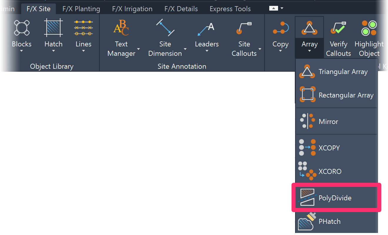
F/X Site ribbon, PolyDivide flyout

F/X Irrigation ribbon, PolyDivide flyout

F/X Planting ribbon, PolyDivide flyout

F/X Admin, F/X Site, F/X Planting, or F/X Irrigation menu, PolyDivide option (F/X Admin menu shown as an example)
or type POLYDIVIDE in the Command line
You'll be prompted to Select object. Select a closed polyline object you want to divide.
In this example, we'll select a labeled groundcover area, pictured to the right.


The Poly Divide dialog box will open.
1. The area of the selected region to be divided, expressed in the units you've specified in your drawing.
2. Split exactly along a specified segment: Choose this option to select or create a segment that will serve as the splitting point of the area.
3. Divide into equal sections: Choose this option to split the area into up to 15 sections.
4. If you chose to divide the area into a number of equal sections, select the number of sections. You'll also see the square area of each of those sections next to each possible number.
Click OK when finished.
Quick video
The cursor will turn into a pickbox, and you'll see the following prompt in the Command line:
Setting Xhair angle -- select entity, enter angle <0>, or click to specify.
To set the angle of the section division(s), you can choose to:
- Click to select a line segment (i.e., entity)
- Enter an angle value (or right-click to set a value of 0)
- Set the angle manually (i.e., click to specify)
In our example, we'll click two points to set the angle manually, as pictured to the right.
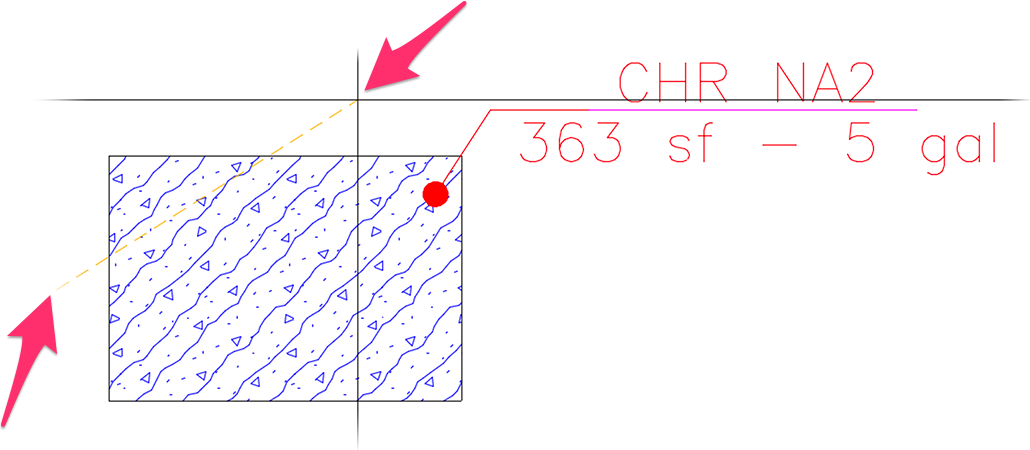
Are you seeing this error message at this point? If so, it's because the angle you selected is crossing two separate portions of the hatch, which will prevent PolyDivide from working correctly.
If you see this error, choose a different angle or split the hatch (manually or using PolyDivide) at a point that separates the two parts into two different hatches.

The region will be divided into the number of equal sections you selected at the specified angle. (In our example, we'ver chosen 4 sections.)
Note that in our example, the plant quantity in the label has remained the same even though the planting area is now divided into four equal sections.
In this case, we'll just run the Verify Labels tool.
The unlabeled planted sections will be highlighted in cyan, and the original plant label will update to show one-fourth of the original number of plants.
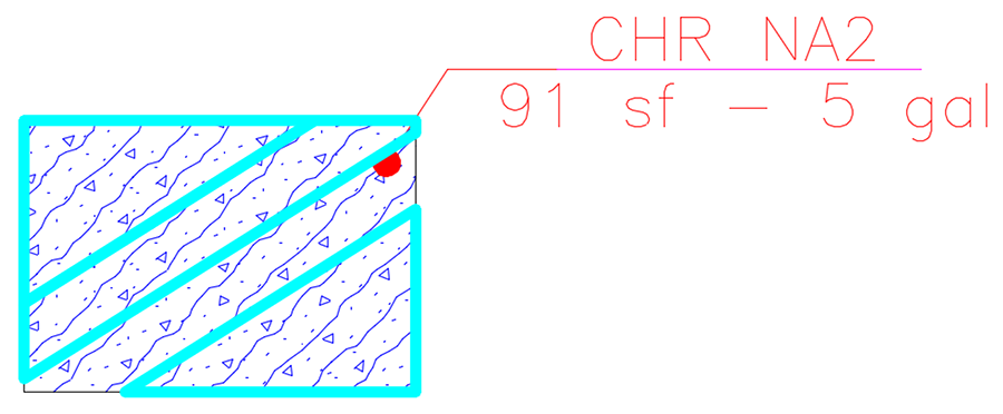
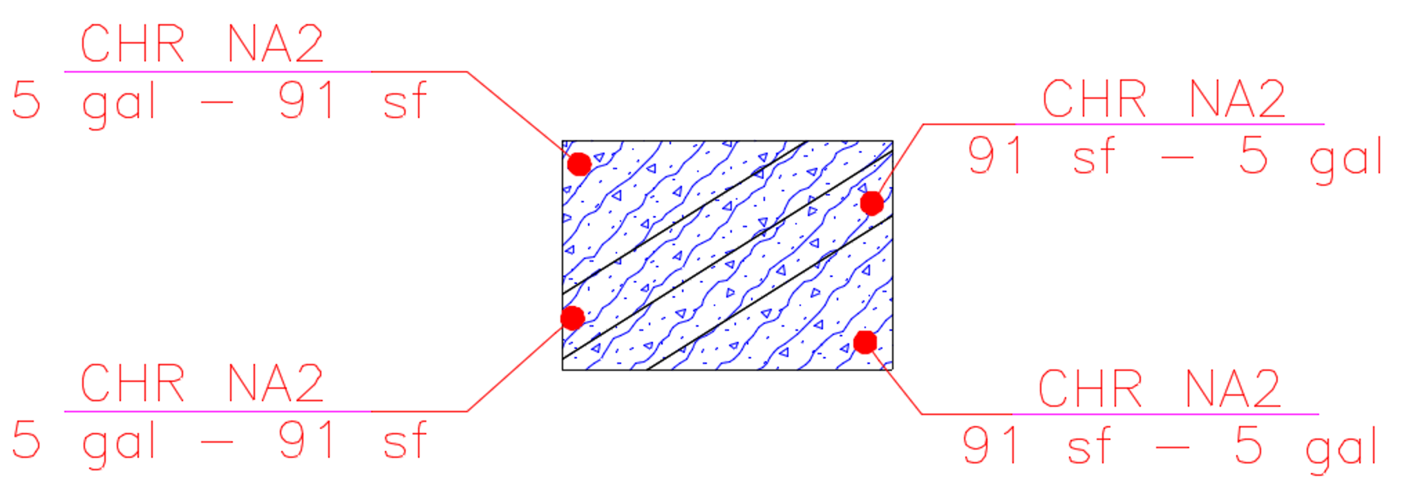
We can now label the unlabeled sections and move the original label so it's visibly within the group of plants it's calling out. Each label will reflect the equal number of plants in its section.
How PolyDivide Works, Including Complex Shapes
When you specify that you want to split exactly on the segment specified, whether you select a polyline/line or draw a segment with two points, PolyDivide will use that exact segment. Note that the tool will look for that segment to intersect the boundary in exactly two points – no more and no less.
If you're targeting a certain number of areas, the system needs to move your cutting segment back and forth. As a result, it won't log the two points of the segment selected, but will instead only log the angle. It will then calculate the geometric center of the boundary and create a cutting segment of infinite length at the angle specified. It will slide this cutting segment back and forth, still looking for only two intersections.
What this all means: Running PolyDivide on an extremely complex shape – an uppercase E, for example – will result in more than two intersections. Because of the way that Region modelers work in CAD, the tool will fail in this case. PolyDivide converts the bounding polyline to a Region and then uses the REGION command to compare areas and determine whether the pieces belong with the left or right portion. So it fundamentally has no alternative but to see more than two regions as an error. It could theoretically loop through all created regions and try them in all possible combinations, but this action would cause wild results, making the operation take much longer.
With a complex shape boundary, your best bet is to use the Split exactly only segment chosen option to cut the boundary into more singular polygonal shapes, and then use the automatic option to divide it up further.
Related Webinars
- Planting F/X for Beginners Part 2: In this second installment, we'll dive right into some of the tools you need to know about for the best experience and fastest workflow when starting with Land F/X planting plans, including PolyDivide. (1 hr 3 min)
Troubleshooting
Issue: Error: Unable to Snap to Geometric Center when selecting a closed polyline with Poldivide active
Issue: Polydivide Error: Angle specified does not intersect polygon appropriately


