Mainline Piping (Draw Mainline Pipe)
Quick video
- Before Drawing Mainline Pipe: Set Selection Cycling to -2
- Draw Mainline Pipe
- Valve-in-Head (VIH) Rotors (Use our Draw Laterals Tool)
- Using Multiple Pipe Classes
- Mainline Error Checking
- Mainline Graphic Adjustments
- Insert Pipe Sleeves
- Joint Restraint Fittings
- Mainline Pipe Information
- Related Webinars
- Troubleshooting
With our Draw Mainline tool, you'll draw a polyline that will double as your mainline pipe, connection your water source to any valves in your system.
We recommend reviewing the Pipe Data to determine the type of mainline pipe that will be used on your project before beginning the piping process.
Before Drawing Mainline: Set Selection Cycling to -2
Before you start drawing mainline pipe, make sure to set the Selection Cycle system variable to -2. This setting will prevent a selection dialog box from popping up as you pipe your mainline, which in turn requires extra mouse clicks.
Type SelectionCycle in the Command line and press Enter. When prompted to enter a value, type -2 (that is, minus 2).
Draw Mainline Pipe
Open our Draw Mainline tool:
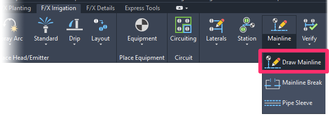
F/X Irrigation ribbon, Draw Mainline flyout
or type MainlinePipe in the Command line
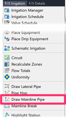
F/X Irrigation menu, Draw Mainline Pipe option
The cursor will turn into a pickbox to begin the drawing process, and the layer LI-PIPE-MAIN-NPLT will turn on automatically.
This layer is the non-plot layer for Initial Mainline Layout, if you decided to use that optional feature to assist in the mainline layout process. When you exit the Draw Mainline tool, this layer will turn off automatically.
The idea is to allow the Initial Mainline Layout to be a guide for how you intend the mainline to be drawn. You can start at a logical point, such as the Point of Connection (POC), such as a water meter, and the function will “snap” to that (and any mainline) object. Next would be to pipe to the backflow device, if on the drawing, and let the Initial Mainline Layout be a directional guide for your intention of the mainline location. Keep clicking or drawing to points in space, where you might change direction, or clicking and “snapping” to a mainline object, such as a remote control valve, quick coupler, hose bibb, master valve, flow sensor, etc.
When you select a mainline object, point in space, or a mainline pipe, the object, point, or pipe connection will be highlighted to let you know you selected it.
The Command Line will prompt: Next point or valve {<X>hair angle, <A>rc, <C>lass, <T>oggle layers}.
You can then either draw as indicated above, or press one of the following keys:
- number keys (1 through 9) to toggle to the corresponding pipe category you've added in the Pipe Data (for example, press 2 to toggle to Category 2)
- X for "Xhair Angle"
- A to draw the pipe as a graphical arc, for better readability
- C to toggle between pipe categories if you added more than one type of lateral pipe to your project
- T to toggle layers to see just mainline information.
In addition, you can always type U for "Undo," which will undo previous functions.
“X” for Xhair Angle
Typing "X" will activate Xhair Angle (formerly known as Snap Angle) – a tool that allows you to orient your crosshairs (thus how you are going to control drawing your pipe) by:
- clicking on another line (thus matching the orientation of that line)
- clicking two points in space
- entering a number, or
- right-clicking to bring the crosshairs back to 0 orientation
Press the F8 key or click the Ortho button at the bottom of your CAD window to activate the Ortho function. You can toggle Ortho on and off freely while drawing piping.
“A” for Arc
Typing "A" during piping will allow you to select another point and then define an arc between where you started and ended. This function is intended for a larger graphic arc rather than a pipe hop.
“C” to Toggle Between Classes
If you added more than one class of pipe for the mainline piping during the Pipe Data review, you can type "C" to toggle between the classes of pipe you have added while drawing the mainline. The first type of pipe you added to your project will have a dashed linetype, and other classes will be assigned other types of line graphics, such as dash-dot, etc. The program will keep track of the length of each class of pipe used.
“T” to Toggle Layers
When drawing mainline pipe, you can type "T"to toggle, or turn off, layers relating to lateral lines, such as heads, lateral pipe, lateral pipe sizes, etc. This function will allow the mainline-related objects to stand out more clearly for ease of graphical interface. You can either press T again to turn on the lateral line related layers, or exit the Draw Mainline function. All previous layers will turn back on.
Imagine the Draw Mainline tool as placing actual pipe in the field.
- The mainline pipe you draw will only connect to mainline-related items, such as valves, water meters, backflow devices, fittings, pipe, or simply a point in space that will act as a fitting. It will not connect with non-mainline related items, such as heads, trees, etc.
- The mainline pipe will automatically “snap” to valves, fittings, or pipe if these objects are at the pickbox area of your crosshairs. If you want to place a pipe near an entity, such as a valve, but not snap to it, zoom in closely to select the area and avoid the valve.
-
The order of selection of the Draw Mainline tool for finding and snapping to an entity is:
- Valve or other mainline block
- Pipe fitting
- Pipe that it can insert a fitting into
- A point in space, where the Draw Mainline tool will assume you're piping to an end point fitting.
Valve-in-Head (VIH) Rotors – Use our Draw Laterals Tool
Valve-in-head (VIH) rotors are generally piped with constantly pressurized pipe, which, by definition, is mainline. However, you should use our Lateral Pipe tool when piping to and between VIH rotors. Why? Because our system allows areas connected with lateral pipe to be turned into separate stations or zones – plus many designers refer to these pipes as "laterals." The system will recognize the valves in the heads and will treat the pipe as if it's mainline. See our VIH Rotors page for more information.
Using Multiple Pipe Classes
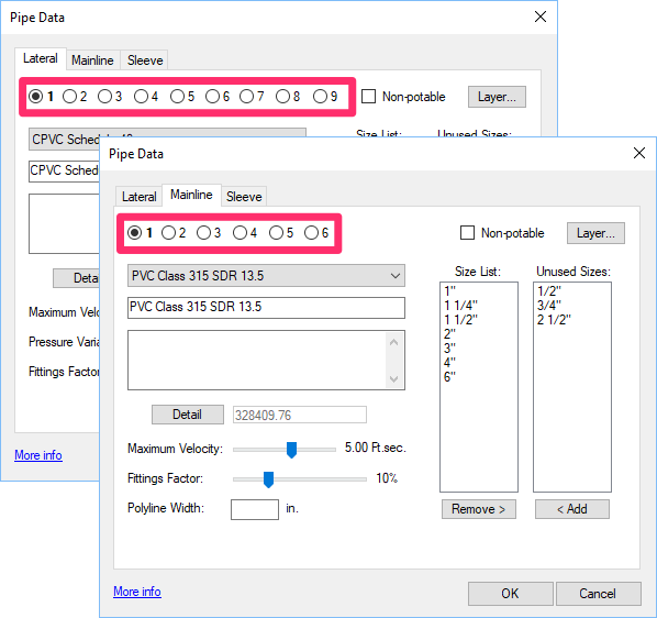
Our Pipe Data tool allows you to specify up to 9 classes of lateral pipe and 6 classes of mainline in each of your projects. As long as you meet a few specific criteria in setting up your pipe classes, the system will automatically assign each of your classes to the correct size of lateral or mainline pipe.
Mainline Error Checking
Verify Mainline
Before you size the mainline, we recommend verifying that you have piped to all valves, quick couplers (or hose bibbs), and any other mainline-related items. The Verify Mainline tool performs a sweep of your entire system design, checking whether your pipes and callouts are error free.
Quick video
For further information, see our Verify Mainline documentation.
Highlight Station
The Highlight Station tool is not really an error-checking feature, but it's a valuable tool for visualizing and evaluating your mainline layout.
For information, see our Highlight Station page.
Mainline Graphic Adjustments
Even when you take great care in drawing a mainline so it does not interfere with the lateral system and other graphics in the drawing, you'll still need to complete some final graphic touchups to the mainline graphic.
Mainline Break
The Mainline Break feature is a way to remove mainline graphics to prevent them from interfering with the lateral system or other graphics.
Open our Mainline Break tool:
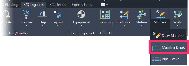
F/X Irrigation ribbon, Mainline Break flyout
or type MainlineBreak in the Command line
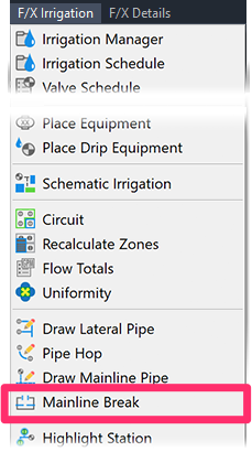
F/X Irrigation menu, Mainline Break option
The cursor will turn into a pickbox. Select a pipe where you want to start and stop the graphic break.

Mainline pipe interferes with the head graphic.

First point of break

Second point of break
The Mainline Break does not alter the length of the pipe. It only makes certain portions of the mainline “invisible,” but the calculations think the pipe is continuous.
Do not use the AutoCAD BREAK command. This command will break everything, and the pipe will no longer be functional.
The black ovals in the image to the right denote four other locations along this length of mainline that interfere with other graphics.


The image to the left shows the drawing after these locations are cleaned up with Mainline Break.
As the mainline is a dashed line graphic, breaking the mainline in this fashion produces a natural look.
Pipe Hop
Placing a manual Pipe Hop is another way to separate the mainline graphically from the lateral line and other graphics.
For information and instructions, see our page on Placing a Manual Pipe Hop.
Do not use any native AutoCAD commands to break or apply arcs in the piping, as this will destroy the pipe data.
Insert Pipe Sleeves
Our Insert Pipe Sleeve tool allows you to insert a sleeve at a pipe of your choice. The sleeve will automatically appear in the Irrigation Schedule.
See our Insert Pipe Sleeve documentation page for a detailed description of the process of placing pipe sleeves – an optional feature.
Joint Restraint Fittings
The joints of larger sizes of mainline can be under extreme pressure. These joints often fail due to water hammer, water velocity, etc., and the failures can cause considerable damage and be expensive to repair. One solution on larger mainline sizes is to use joint restraints at the various tees, ells, bends, etc., that occur on a mainline.
Joint restraints are usually ductile iron restraints that clamp onto a pipe at one end and a fitting at the other end. They provide a reliable strengthening of the joint and eliminate the need for a concrete thrust block. The three basic categories of restraints are:
Fitting to Pipe Restraint
This type of joint restraint connects a pipe to a fitting, such as an ell, tee, or bend.
You can place joint restraints at locations where you know they will be needed before drawing the mainline, and the mainline will snap and connect to them. Or you can place them after you have drawn the mainline.

Pipe to Pipe Restraint
Lengths of straight pipe will require pipe-to-pipe restraints for additional support at certain intervals along the length of the pipe.

Valve to Fitting Restraint
As the name implies, this type of joint restrains provides a connection between a valve and a pipe or fitting.

A few of the details in our detail library depict some typical uses of joint restraints. Here's an overall preview of some of those details:

See our Details section for information on accessing the F/X Detail Library.
Adding Joint Restraints
We provide instructions for adding a joint restraint fitting on our Adding Auxiliary Equipment page.
Placing Joint Restraints Before Piping the Mainline
Place joint restraints where you feel they will be required along the Initial Mainline Layout, if you used that optional method of initially expressing the location of the mainline. You'll pipe to the joint restraints later when you draw the mainline.

Placing at the Initial Mainline Layout (purple line)

The joint restraint is placed at the tee location.

When you draw the mainline, it will "snap" to the joint restraint symbol.

The finished mainline drawn with the joint restraint
Placing Joint Restraints After Piping the Mainline
Draw your mainline as you want it to be laid out, then place joint restraints along the mainline at the appropriate locations.

Joint restraint to be placed at tee in mainline

The restraint symbol will "snap" to the tee location.
Here's an example Irrigation Schedule that includes joint restraints:

Mainline Pipe Information
For general information about mainline pipe, see the Mainline Pipe article in our Irrigation Equipment documentation.
Related Webinars
- Irrigation for Beginners: We'll show how to navigate through the Irrigation ribbon and build a familiarity with our conceptual-level tools. You'll also learn the basics of adding equipment to a project, placing, piping, sizing, and scheduling. (1 hr 45 min)
- Getting Started with Irrigation F/X: This tour and tutorial will help you make the most of everything Irrigation F/X has to offer. We start with the fundamentals, such as how to set up your projects and Preferences, before diving into our collection of time-saving irrigation design tools. (59 min)
- Irrigation Tools – What You Need to Know: We'll show you the ins and outs of basic irrigation setup using our software. You'll also learn the essentials of placing equipment such as drip, sprays, and rotors. (1 hr 6 min)
- Irrigation Tips & Tricks: We'll show you some advanced tools you may or may not know about. You'll also learn techniques and best practices that will help speed up your workflow. (1 hr 3 min)
- Existing Irrigation: Learn the techniques, tools, and tricks you'll need to expand an existing system, including how to use a pipe cap to account for existing flow and add new valves to an existing mainline. (56 min)
- Advanced Irrigation Troubleshooting: Learn to think like a Land F/X irrigation troubleshooter. We'll show you why your symbols don't match, why you would see the message "Error accessing equipment data" (and how to fix these issues, as well as tips on pressure losses and precip rates, pipe caps, system monitors, and flow zones. (1 hr 3 min)
- Golf Course Irrigation: We'll demonstrate some of the great tools Irrigation F/X offers to help ensure proper mainline sizing and scheduling. We'll also discuss the use of using flow zones, shut-off valves, and valve-in-head rotors. (1 hr 4 min)
- Connecting Flow Sensors in Complex Situations: Norm Bartlett from Creative Sensor Technology (CST) reviews common connection problems, such as sharing a flow sensor between multiple controllers, measuring flow in systems with multiple POCs, and connecting new flow sensors and master valves without disrupting existing landscape or hardscapes. (1 hr 1 min)
- Efficient Irrigation for Small Spaces: Chris Roesink from Hunter takes you through the challenges of and solutions to irrigating in restricted areas. (1 hr 8 min)
- Learn all about the relationship between pressure in a mainline and how changes in PSI can influence downstream flow rates. Presented by Bob Beers (and Chris Wright) of Baseline, this webinar reviews several solutions to for capturing PSI readings within a hydraulic structure. (47 min)
Troubleshooting
Issue: CAD becomes extremely slow, or cursor lags or becomes jumpy, during piping
Issue: After laying out your pipes, you discovered that you used the wrong pipe class
Issue: You need to run multiple (two or more) valves at a time
Issue: Your mainline pipe is coming in too thick
Issue: Lines in your Xrefs are becoming excessively thick when you draw mainline pipe
Issue: You want to use custom linetypes for different pipe sizes


