
Valve Callouts & Renumbering Valves
Quick video
- Updated Valve Callout Dialog Box (2023)
- Valve Callouts Overview
- Placing Valve Callouts
- Editing Already-Placed Valve Callouts
- Default Valve Callout Types
- Valve Callouts and Slope Areas
- Related Webinars
- Troubleshooting
Calling out a valve will create a symbol listing the valve's number, flow, and size. You may wish to select a specific style of valve callout of your choice in the Irrigation Preferences. You can also include other pieces of information with additional attributes.
At any point after a valve has been placed, you can call it out. Resizing the valve's lateral pipes will automatically update the callout with the correct flow for the valve. After you call out a valve, the valve schedule will identify it using the number you've assigned it. Our Valve Callout tool also allows you to renumber your valves.
Looking for a way to edit and customize your valve callouts? See our article on modifying our updated valve callouts.
Updated Valve Callout Dialog Box (2023)
We've made some major improvements to our Valve Callout tool with an update in February 2023, including an overhaul of the dialog box that pops up when you open the tool. Read on to see the improvements we've built into this update.

Valve Number dialog box (pre-update)

Valve Callout dialog box (post-update)
Valve Callouts Overview
Access the Valve Callout tool:

F/X Irrigation ribbon, Valve Callout/Renumber flyout
or type ValveCallout in the Command line

F/X Irrigation menu, Valve Callout option
The cursor will turn into a pickbox, and the Command line will prompt you to Select valve.
Click a valve in your drawing to call out.
The Valve Callout dialog box will open.

1. Controller: If you've placed one or more controllers, the system will pick them up and you'll see them as options to select. (Examples: A1, A2, A3, where A = the controller). You can leave this field blank if you want to number your valves as a simple 1, 2, 3, 4. More information
2. If you want to separate the controller letter from your valve number, you can choose Hyphen ( - ), Decimal ( . ), or Nothing. More information
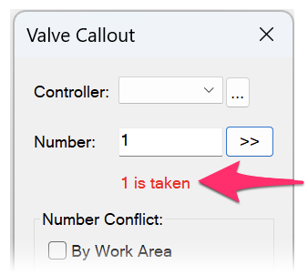
3. Number: This field will default to the next available valve number as a suggestion for numbering the valve you selected. You can choose to add your own number. More information
4. Click the >> button see all valves called out based on the controller type selected. More information
5. Number Conflict: Options for whether to allow repeated valve numbers and, if so, how you want the system to handle them:
- By Work Area: This option will be grayed out if no Work Areas are detected in your drawing, but will be selectable if Work Areas are present.
- Duplicate this number: Select this option if you want to allow the system to use the same valve number in different areas of your drawing, but don't want to place Work Areas.
- Increment other valves: Select this option if you want to pick a number that is taken (for example, changing from #1 to #2) and have the numbers of the remaining called-out valves shift accordingly.
Controller
Open the Controller menu to select from the available controller list, based on which controllers have been placed in the drawing.
If no controllers have been placed, you can select Add New, give the controller a single-letter identifier, and click OK.
If By Work Area is selected in the Number Conflict area, this list will be filtered to just show controller options within each applicable Work Area.

Delimiter Options

Click the ... button to the right of the Controller menu to see delimiter options.
You'll now see the following options:
- Hyphen (-) – examples: A-1, A-2, A-3
- Period (.) – examples: A.1 A.2, A.3
- Nothing – examples: A1, A2, A3
Select the format you want to use when displaying the controller and valve identifiers in your valve callouts.

This setting should typically be applied once per project and kept consistent through the project. If you introduce multiple delimiters into your callouts, the system will remember the last delimiter setting chosen when labeling. And when renumbering, it will only adjust all the same delimiter types.
Numbering Valves
The Number field will default to the next available valve number as a suggestion for numbering the valve you selected. If you enter your own callout number, the preview will show as either taken or available:

If you choose to enter your own valve number, you can use a simple number, such as 1, 2, 3, etc., or a number and a letter, such as A1, A2, A3, or A-1, A-2, A-3, etc. Valve numbering is now automated, so, for example if you enter number A1, the A will simply be moved into the Controller list and allow you to select it. Subsequent valves will then be numbered automatically from that point.
Options for Existing Valve Callouts
Click the >> button to the right of the Number field to see options for handling existing valve callouts.

You'll now see an Existing list showing existing valve callout numbers in your drawing (if any). You'll also have the following options:

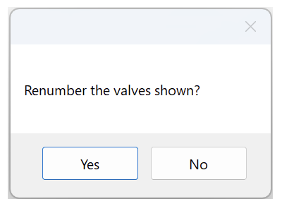
1. Renumber: If you click this button, you'll be asked whether you want to renumber the valves shown. If you click Yes, the valves will be renumbered and the gaps in callout numbering will be closed automatically.
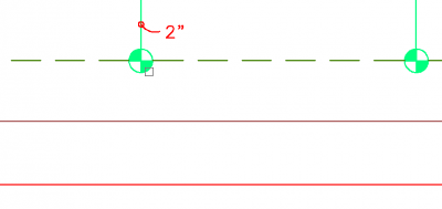
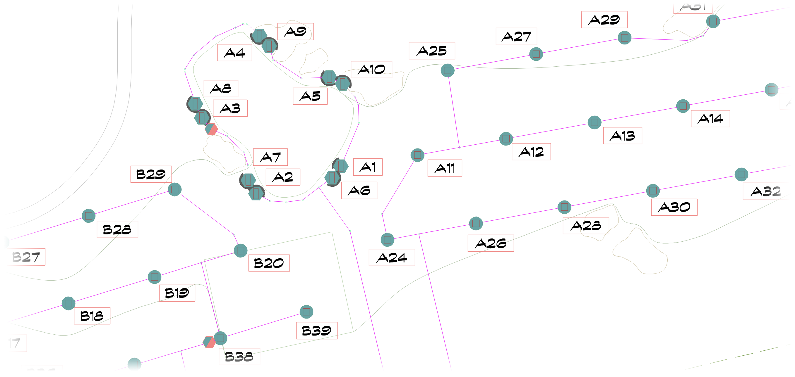
2. Locate Valve: If you select a callout from the list and then click the Locate Valve button, you'll be taken to that valve and it will be highlighted, as pictured to the right.

3. Renumber all valves: If you select this option, the selected valve, along with all subsequent valves in the Existing list will be renumbered using the Valve Callout tool. This checkbox will only be visible under all of the following conditions:
- The valve is already called out.
- The side popout is extended.
- Other valves are numbered after the existing one that was selected.
- The new number that has been entered does not create a numbering conflict.
Placing Valve Callouts
After making your selections in the Valve Callout dialog box, click OK to begin placing the callout. Then click within your drawing to place the callout. The Command line will then prompt: Callout location.
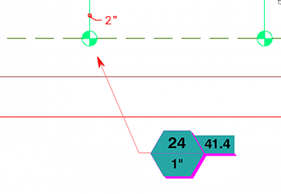
Select the general direction where you want the callout to be oriented by clicking either to the left or right of the leader endpoint. Finally, the Command line will prompt: Arrow location, <no arrow>.

If you want an arrow drawn to the valve, click a point to indicate the length of the leader you want.
We've added background masks to our valve callouts to provide better contrast in your drawings. The default color of these masks is Color 133 (as pictured to the left). If you don't like this color, you're free to change it when customizing your valve callouts. Not seeing your text in your valve callouts, or are they plotting all black, including the text? Here's what to do.
You can click to place the arrow directly in the center of the valve, as pictured above, or place it near the valve, as pictured to the right.

If you'd rather not have an arrow pointing to the valve, and prefer to organize your valve callouts in a common location, you can right-click. The valve number will instead appear next to the valve.
If you'd prefer to place the callout near the valve, with neither an arrow nor a number, press the Esc key when prompted for the arrow.
If you opt for a callout with no arrow, a valve number in the same font as the text in your callout will automatically appear next to the valve. You can adjust the location of this number for clarity.
Editing Already-Placed Valve Callouts
If you need to edit a valve callout you've already placed, just open our Valve Callout tool, click the valve in your drawing, and make any necessary adjustments in the Valve Callout dialog box.
Default Valve Callout Types
The thumbnail image under Valve Callouts in the Irrigation Preferences screen shows the default callout style that will be used for valves. You can click this thumbnail and select a new Valve Callout style as needed.

You can also make changes to your valve callout settings by editing the equipment:
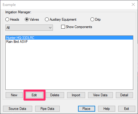
Select the equipment to edit in the Irrigation Manager and then click Edit.
To select equipment to edit that you've already placed in your drawing, use our Edit Equipment / View Data tool:

F/X Irrigation ribbon, Edit Equipment button
or type EquipInfo in the Command line

F/X Irrigation menu, Edit Equipment option
Then select a valve in your drawing to change its callout settings.
The Equipment Info dialog box will open.
Click Callout to select a different callout style for the selected valve.

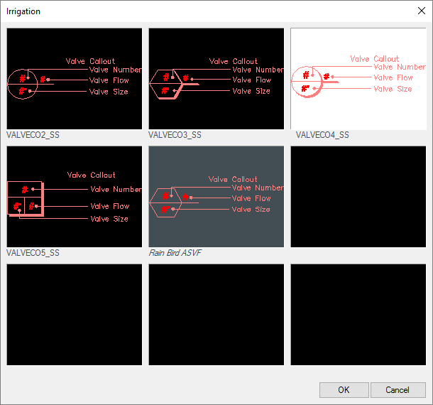
You'll now see a dialog box with the thumbnail images of the available valve callout styles.
Click one of the thumbnail images to select that callout style.
The callout style you select will be the style our software will use – regardless of what you select in the Preferences screen.
If you mistakenly change the callout by editing the valve, you can resolve this issue by editing the valve again and selecting the callout style of your choice.
You should also be able to test that any valve added to the project will use the callout specified in the Irrigation Preferences screen.
Labeling Valve-in-Head Emitters
The example below shows what valve callouts look like when labeling valve-in-head sprinklers. Note that these callouts are different from the standard valve callouts.
Valve Callouts and Slope Areas
Slope Areas work with our Slope Callout tool to apply a specific grade percentage or ratio to a closed polyline area in your drawing. Objects represented by any smart hatches within those closed polylines (Slope Areas) will have their quantity, volume, or area recalculated based on that slope percentage or ratio.
If you place a Valve Callout in a drawing that includes one or more Slope Areas, the tool will scan all All Areas for Dripline to determine whether they are inside a Slope Area. If so, the schedule will recalculate those areas' flow rates based on the slop factor and the change in square footage/meters.
Related Webinars
- Getting Started with Irrigation F/X: Take a walk through Irrigation F/X and see how our smart tools, combined with a proper setup, make irrigation design faster and smoother. We'll cover how to get your drawings off to the right start, explore features that streamline everyday tasks, and share some practical tips directly from our irrigation usage support team. (1 hr 4 min)
Troubleshooting
Issue: Some of my valve callouts are not resizing (rescaling) when I rescale my drawing
Issue: You saw a Missing File error when placing valve callouts
Issue: Your valve callout text is not showing up (but your callouts are)
Issue: One or more of your valve callouts shows the wrong valve size or displays strange characters
Issue: Your valve callout arrows are hollow, not solid, or displaying as lines only
Contact
- Land F/X


Our software tailors AutoCAD®, Revit®, SketchUp®, and Rhino® to the needs of landscape architects, irrigation designers, and other professionals. We automate your most tedious tasks and ensure accuracy, giving you more time to design.